


- 홈
- Blogs
- Power management
- What Is an IGBT? The Insulated Gate Bipolar Transistor Explained
What Is an IGBT? The Insulated Gate Bipolar Transistor Explained

Pull away from a stoplight in a Tesla, and a cluster of semiconductor switches under the floor spins the motor by converting battery DC into three-phase AC, thousands of times per second. Board a Shinkansen in Japan, and the traction drive runs on that very type of switch, rated at triple the voltage. Walk past a rooftop solar installation, and you'll find the same technology inside the inverter pushing power onto the grid.
The component tying all three together is the IGBT.
IGBT stands for Insulated Gate Bipolar Transistor. It's a three-terminal power switch that turns heavy electrical currents on and off: hundreds of amps at thousands of volts. Dr. B. Jayant Baliga built the first practical IGBT transistor at General Electric in 1982, and adoption spread quickly. Within a decade, IGBTs had displaced older components in motor drives, inverters, and power supplies across industries.
If you already understand how a transistor works at a basic level but aren't sure what makes the IGBT different, this article walks through everything from schematic symbol to silicon.
Key Takeaways
An IGBT is a voltage-controlled power switch that pairs a MOSFET's easy gate drive with a bipolar transistor's high-current capability.
Rated from 600 V to 6,500 V and up to hundreds of amps, IGBTs handle power levels where MOSFETs can't compete.
The tradeoff is switching speed: tail current during turn-off limits practical frequencies to around 20-50 kHz.
Primary applications include EV traction inverters, variable-frequency motor drives, solar/wind inverters, and railway traction systems.
IGBTs come as discrete single devices or as pre-assembled modules with multiple dies, diodes, and optimized thermal paths in one package.
Silicon carbide (SiC) MOSFETs are displacing IGBTs in some high-frequency EV applications, but IGBTs remain dominant above 3,300 V and in cost-sensitive designs.
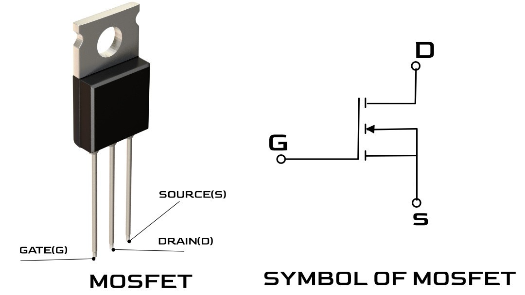
Reading the IGBT Symbol

You can spot an IGBT on a schematic right away, and the symbol itself reveals how the device behaves.
The gate terminal sits to the left, separated by a visible gap from the rest of the symbol. That gap represents the insulated oxide layer, the same concept behind a MOSFET gate. No current flows into it. You control the IGBT with voltage alone, which keeps drive circuitry simple and inexpensive.
Collector and emitter terminals borrow both their names and their behavior from bipolar transistor conventions. An arrow on the emitter points inward (for an N-channel IGBT), indicating the direction of conventional current flow. If you're familiar with different transistor types and their functions, the symbol looks like a MOSFET input grafted onto a BJT output. That's a fair description of what happens inside the silicon, too.
One thing you won't see on the IGBT symbol: a body diode. MOSFET symbols include one by default. IGBTs don't. When a circuit requires reverse current flow (and most power circuits do), a separate freewheeling diode sits alongside the IGBT. Packaged IGBT modules typically include these diodes inside the unit already, which is one reason modules are so popular in production designs.
How an IGBT Works
At the simplest level, an IGBT is a voltage-controlled power switch. Apply a positive voltage to the gate (relative to the emitter), and current flows between collector and emitter. Remove that voltage, and current stops. A small control signal governs a much larger power flow, which is the whole reason engineers reach for IGBTs when they need to switch serious loads.
The interesting part is what happens between those two states.
Inside the Silicon
An IGBT stacks four semiconductor layers: P-N-P-N from collector to emitter. The top portion of that stack works as an N-channel MOSFET. The bottom portion acts as a PNP bipolar transistor. When gate voltage exceeds the threshold, the MOSFET creates an inversion channel and pulls electrons into the N- drift region. So far, standard MOSFET behavior.
Here's the twist. The P+ collector layer at the bottom injects holes into that same drift region. Now you've got both electrons and holes flooding the area, and resistance drops sharply. Engineers call this conductivity modulation, and it's the reason a power IGBT holds a low voltage drop even while carrying hundreds of amps. A MOSFET at the same voltage rating can't match that performance; its on-state resistance climbs as current increases.
One historical note: early IGBTs contained a parasitic thyristor structure that could "latch up," locking the device permanently on. That failure mode plagued designs until non-latch-up structures appeared around 1984. Modern devices don't suffer from it.
The Turn-Off Tradeoff
Turning an IGBT on is quick. Turning it off takes longer, and the cause traces back to conductivity modulation.
When you pull the gate voltage to zero, the MOSFET channel shuts immediately. But all those injected carriers still sitting in the drift region need time to recombine. Until they clear out, a residual "tail current" keeps flowing through the collector-emitter path. This tail current is the main penalty you pay for the IGBT's low on-state voltage. It caps practical hard-switching frequencies at around 20-50 kHz. Beyond that range, switching losses pile up and the IGBT vs. MOSFET decision tips in the MOSFET's favor.
IGBT vs. MOSFET vs. BJT
Three transistor families split the power electronics territory along voltage, current, and frequency lines. Picking the wrong one costs you wasted energy, oversized heatsinks, or both. Here's how they stack up:
| Parameter | BJT | MOSFET | IGBT |
| Drive method | Current into the base | Voltage on the gate | Voltage on the gate |
| Practical voltage range | Up to ~1,000 V | Up to ~500 V | 600 V to 6,500 V |
| Switching frequency | Slow (under 100 kHz) | Fast (up to 500 kHz+) | Moderate (up to ~50 kHz) |
| On-state loss at high current | Low (low V_CE(sat)) | High (resistive, rises with I²) | Low (low V_CE(sat)) |
| Gate/base drive complexity | High (continuous base current) | Low (voltage only) | Low (voltage only) |
| Typical role today | Mostly legacy and small-signal | High-frequency, lower-voltage switching | High-voltage, high-current switching |
The practical decision comes down to two variables: voltage and frequency. Below roughly 400 V, at switching speeds above 100 kHz, MOSFETs are the obvious pick. Their resistive on-state characteristics play well at lower currents, and fast switching keeps losses manageable. For circuits running above 600 V with heavy current at moderate switching rates (motor drives, grid inverters, traction systems), the IGBT takes over. Its low saturation voltage means less heat under load than a MOSFET at equivalent voltage ratings.
As for BJTs in power applications? Largely replaced. The need for continuous base current makes them harder to drive and less efficient than voltage-controlled alternatives. You'll still spot them in small-signal amplification and some legacy designs, but new power converters rarely spec a BJT where an IGBT or MOSFET will do the job.

A 1,200 V discrete IGBT like the ON Semiconductor FGL40N120ANDTU sits in the sweet spot for most single-phase and three-phase power conversion applications, and it's a common stocking item at distributors.
Where IGBTs Are Used
Most IGBT applications boil down to one job: converting electrical power from one form to another, efficiently and at scale.
Motor drives and electric vehicles
Variable-frequency drives (VFDs) are the single largest market for IGBTs. Inside a VFD, IGBTs chop DC bus voltage into a synthesized AC waveform that controls motor speed and torque. Across factory floors worldwide, every conveyor belt, pump, and fan with adjustable speed control likely has IGBTs switching behind the panel. EV traction inverters do the same job, converting battery DC (typically a 400 V or 800 V bus) into three-phase AC for the drive motor. Modules rated at several hundred amps handle each phase of the inverter.
Renewable energy and power conversion
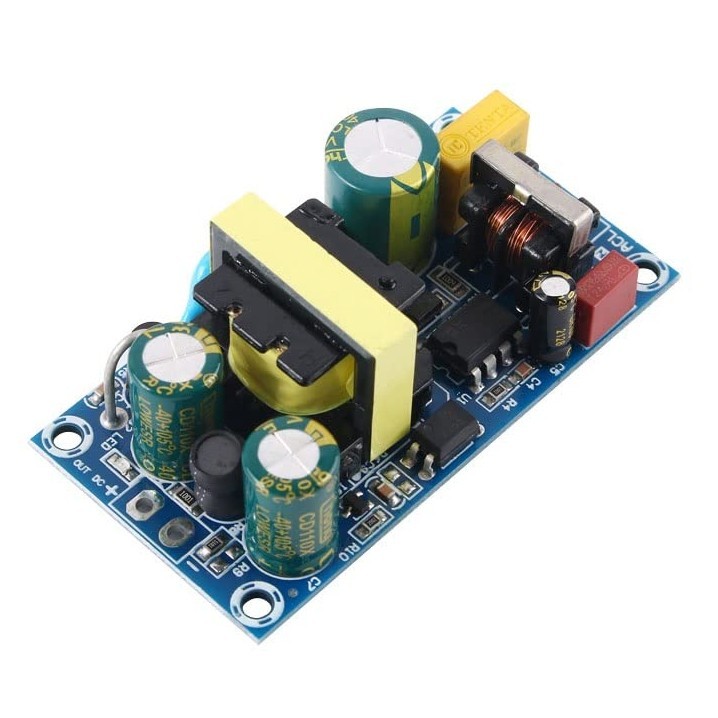
Solar inverters depend on IGBTs to turn panel DC into grid-frequency AC. Wind turbine converters operate on a similar principle at larger scale. UPS systems, too: when mains power drops, IGBTs in the inverter stage keep AC output alive from battery reserves. Devices rated around 650 V, such as the STMicroelectronics STGWA60H65DFB, fit neatly into single-phase solar and UPS designs where that voltage class is standard.
Railway traction and grid infrastructure
This is where high-voltage IGBTs earn their keep. Electric trains and metro systems run traction inverters rated at 3,300 V and up, with mainline rail applications reaching 6,500 V. HVDC power transmission, induction heating, and industrial welding equipment all operate in the kilovolt range. A device like the Infineon IKW25N120H3 covers 1,200 V applications at the lower boundary of this territory; dedicated high-voltage IGBT modules from Mitsubishi and Infineon push well beyond that for rail and grid use.
Discrete IGBTs vs. IGBT Modules
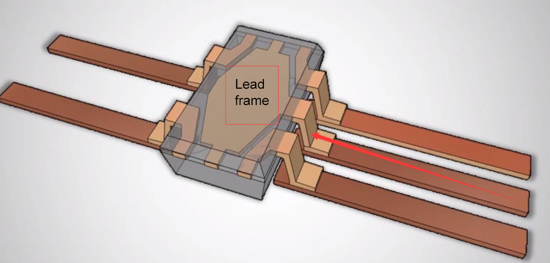
A discrete IGBT ships as a single transistor die in a standard package (TO-247 and TO-264 are the most common formats). You design the half-bridge, gate drive, snubber network, and thermal management around it yourself. That level of control suits prototyping, lower-power converters, and custom circuit topologies well. Single IGBT transistors are available across a wide spread of voltage and current ratings from every major manufacturer.
IGBT modules take a different approach entirely. Multiple IGBT dies and their paired freewheeling diodes share a single substrate inside one package, pre-wired into a useful circuit configuration: half-bridge, six-pack (a full three-phase inverter in one unit), chopper, or boost. Thermal paths come optimized from the factory, with copper baseplates or AlSiC carriers built for direct heatsink mounting. A 600 A module like the Powerex CM600DU-5F replaces dozens of discrete parts and the PCB layout headaches that come with routing high-current traces at tight clearances.
Choosing between discrete and module comes down to flexibility versus integration. Modules carry a higher per-unit price, but they cut engineering time, shrink the physical footprint, and deliver a thermally validated assembly ready to bolt onto a heatsink. For production motor drives, EV inverters, and grid-tied power converters, modules are the standard. The market reflects it: global IGBT module sales hit roughly $6-8 billion in 2024, driven by electric vehicle adoption and renewable energy buildout.
Types of IGBTs
Not all IGBTs are built the same way, and the internal differences affect how fast a device switches and how much abuse it can survive.

Punch-Through (PT)
Punch-through devices include an N+ buffer layer between the collector and the drift region. That buffer speeds up carrier recombination during turn-off, producing faster switching with less tail current. On the downside, PT IGBTs tolerate shorter short-circuit events and carry less thermal margin. You'll find them in high-frequency applications like switch-mode power supplies and UPS inverters where switching speed matters most.
Non-Punch-Through (NPT)
Non-punch-through devices drop the buffer layer. Their drift region runs thicker, switching slows down, but the device handles harder operating conditions. Longer short-circuit withstand capability and stronger thermal resilience make NPT the go-to choice for industrial motor drives and applications where reliability ranks above switching performance.
Field-Stop (FS)
Field-stop designs landed on a middle ground that has mostly replaced both predecessors. A thin buffer layer stops the electric field before it reaches the collector, delivering near-PT switching speed with NPT-level ruggedness. The vast majority of new IGBTs use a field-stop structure, often combined with trench-gate technology (where the gate channel runs vertically into the silicon instead of along the surface) to reduce on-state losses further. Infineon's TRENCHSTOP family is one of the more visible commercial examples of this approach.
Quick reference:
| Type | Buffer Layer | Switching Speed | Ruggedness | Common Applications |
| Punch-Through (PT) | Yes (thick N+) | Fast | Lower | SMPS, UPS inverters |
| Non-Punch-Through (NPT) | No | Slower | High | Motor drives, industrial |
| Field-Stop (FS) | Yes (thin) | Fast | High | Most modern designs |
IGBTs and the Rise of Silicon Carbide
Silicon carbide (SiC) MOSFETs have been eating into IGBT territory for the better part of a decade, and the shift is real. Tesla's Model 3 was the highest-profile case: its traction inverter swapped silicon IGBTs for SiC MOSFETs, gaining faster switching, lower losses, and better high-temperature performance. Other automakers followed, especially on 800 V EV platforms where SiC's advantages are hard to pass up.
So are IGBTs heading for obsolescence? Not close.
SiC MOSFETs excel in a specific band: high switching frequencies, moderate currents, and applications where efficiency gains justify the steeper component price. But SiC wafers cost more to manufacture, and the devices don't scale gracefully into very high voltage ranges. Above 3,300 V, silicon IGBTs still own the market with no production-ready SiC alternative. Cost-sensitive industrial drives, lower-frequency converters, and railway traction systems will keep specifying IGBTs for years to come.
The realistic picture is coexistence, not replacement:
Where SiC wins: high switching frequencies, 800 V EV platforms, compact designs where efficiency gains offset the price premium.
Where IGBTs hold: above 3,300 V, cost-sensitive industrial drives, railway traction, grid infrastructure, and any application where proven reliability at scale matters more than peak switching performance.
A few manufacturers are even experimenting with SiC IGBTs (combining the wide-bandgap material with IGBT device topology for ultra-high-voltage use), though commercial availability remains limited.
Four decades after Baliga's prototype at GE, the IGBT remains one of the most deployed power semiconductors on the planet. It won't top every spec sheet in every application, but for high-voltage, high-current switching at a price point that makes engineering and economic sense, nothing has replaced it. For power converter, motor drive, or inverter projects, discrete IGBT transistors cover a full range of voltage and current classes, and IGBT modules offer integrated, production-ready assemblies.
FAQs
Articles you may also like
Principles and applications of LDO
Working principle of field Mosfet transistor triode
Basic knowledge and working principle of AC to DC converter
A Method for Optimizing the Gate Drive of SiC MOSFETs


