













- Home
- Blogs
- Power management
- What are AC/DC and DC/DC converters?
What are AC/DC and DC/DC converters?
First, we will examine the concepts of AC and DC.
What exactly is AC?
Alternating Current is an abbreviation for Alternating Current.
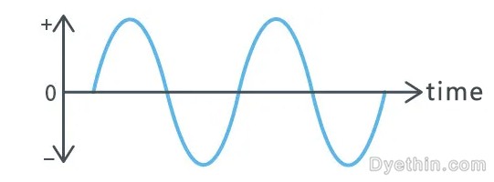
AC is an electric current whose magnitude and polarity (direction) vary periodically over time.
The frequency is the number of times the polarity of the current reverses in one second and is measured in Hertz (Hz).
What is a DC?
The abbreviation for direct current.
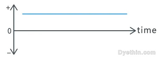
The polarity (direction) of a DC current does not alter over time.
DC refers to a current that neither varies in polarity (direction) nor in magnitude with time.
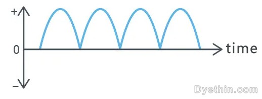
The current whose polarity remains constant over time, but whose magnitude varies, is also DC and is commonly referred to as ripple current (Ripple current).
1.AC/DC Transformer
What is the function of an AC/DC converter?
An AC/DC converter is a component that converts alternating current (AC) voltage to direct current (DC) voltage.
Why is an AC/DC converter necessary?
Because residences and buildings receive 100V or 200V AC voltage, this is the case. However, the majority of our electrical appliances operate on 5V or 3.3V DC voltage. Thus, appliances cannot function unless AC voltage is converted to DC voltage.
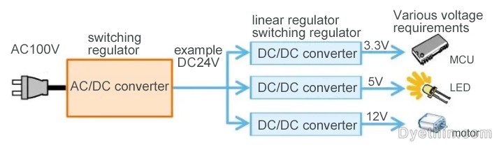
There are also products that can be powered by AC voltage, such as motors and light bulbs. However, the motors are connected to the control circuit of the microcontroller, and the light bulbs have been converted to energy-efficient LEDs, necessitating AC-DC conversion.
Why is AC transmission used?
One could reason, "Since appliances use DC, why not transmit DC in the first place?"
As is common knowledge, electricity is generated by hydroelectric, thermal, nuclear, and other power plants. These power plants are located in mountainous or coastal regions where transmission of AC voltage to urban areas is more advantageous.
By conveying AC voltage at high voltage and low current, it is possible to reduce transmission loss (energy loss). However, since high voltage cannot be used directly in a real home, it must be transformed (stepped down) through a series of substations and then converted to 100V or 200V before entering the home. AC is also simpler for these conversions, so AC voltage is transmitted.
Full-wave and half-wave rectification (AC-to-DC conversion).
There are two methods for converting AC (alternating current voltage) to DC (direct current voltage): full-wave and half-wave rectification. For rectification in both instances, the forward current flow characteristic of the diode is utilized. Dyethin Electronics distributes a variety of diode models, as well as factory-authorized, authentic products.
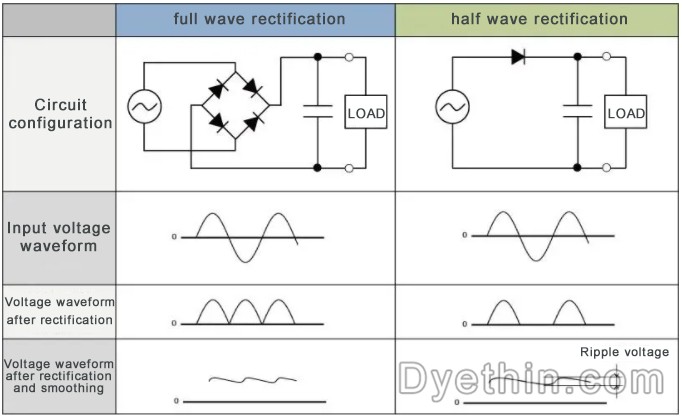
Through a diode bridge circuit structure, full-wave rectification converts the negative voltage component of the input voltage into a positive voltage, and then rectifies it into a DC voltage (pulse voltage). Using a diode, the half-wave rectification eliminates the negative input voltage component and converts it to a DC voltage (pulse voltage). The capacitors' charging and discharging functions are then used to flatten the waveform, resulting in the conversion to pure DC voltage.
Full-wave rectification is therefore a more efficient rectification method than half-wave rectification, which does not utilize input negative voltage components. In addition, the ripple voltage varies based on the capacitor's capacity and load (LOAD).
Under identical capacitor capacity and load conditions, the ripple voltage of full-wave rectification is less than that of half-wave rectification. The lower the ripple voltage, the greater the system's stability and efficacy.
AC/DC conversion procedure
AC/DC conversion utilizes both a transformer and a switch.
Transformer technique
This is a typical transformer-based AC/DC converter circuit configuration.
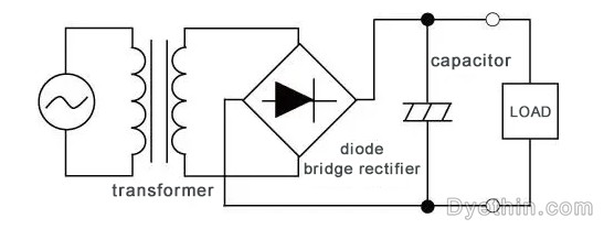
The transformer method begins by reducing the AC voltage to an appropriate AC voltage (from AC100V to AC10V, etc.) using a transformer. This is an AC-to-AC conversion, and the step-down value is determined by the transformer's winding ratio.
Next, the transformer-stepped-down AC voltage is rectified by a diode bridge rectifier and converted into a pulse voltage. Traditional AC-to-DC conversion concludes with the capacitor smoothing and outputting a DC voltage with minor ripples.
The diagram below depicts the transformation of the voltage waveform in transformer mode.

change state
This is the structure of a typical switch-mode AC/DC converter.
The transformer method reduces the AC/AC voltage through the transformer, while the switch method rectifies the AC voltage directly with a diode bridge rectifier. Since the standard household voltage is 100V or 200V, the diode bridge rectifier must have specifications that allow it to withstand high voltage.
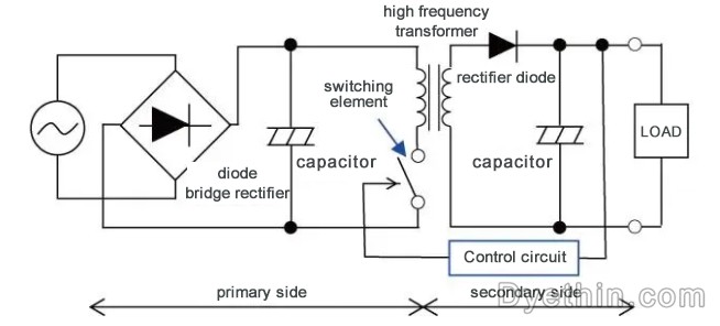
The DC voltage (pulse voltage) is then regulated with a capacitor. Additionally, capacitors need capacitors with a high voltage resistance. Then, the DC voltage is sliced (cut) by the ON/OFF operation of the switching element, and it is transmitted to the secondary side via a high-frequency transformer. At this juncture, the waveform is transformed into a square wave.
Compared to domestic frequencies (50/60Hz), switching elements are utilized at higher frequencies (e.g., 100kHz). Due to the high-frequency operation, the transformer can be miniaturized and made transportable.
The graph below illustrates the varying transition mode voltage waveform.

On the secondary side, a rectifier diode performs half-wave rectification of the square wave, and then a capacitor smoothes it to produce a direct current voltage.
Using a control circuit to control a switching element to attain a stable expected DC output (such as DC12V) is the switching method.
Unlike the transformer method, the switch method consists of switching elements and a control circuit, with a more complex circuit structure. On the other hand, since high-frequency control permits the use of a small transformer, it contributes to the miniaturization of apparatus, which is a significant advantage.
What is the function of Feedback Control?
Switching AC/DC converters monitor the actual DC output voltage and control the switching elements based on the voltage data to guarantee stable realization of the desired DC output. This process of verifying the output voltage to control the switching element is known as feedback control (FB control).
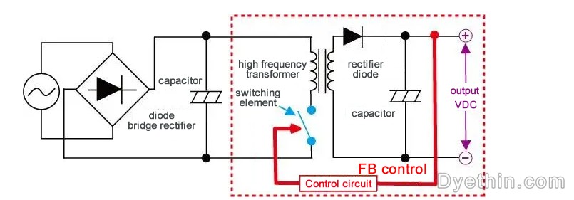
To convert AC voltage to DC voltage, switching AC/DC converters rectify the AC voltage with a diode bridge and level it with a capacitor. Then, a switching element chops (ON/OFF) this DC voltage, which is then stepped down by a high-frequency transformer and transmitted to the secondary side, where it is flattened by a capacitor and a predetermined DC voltage (VDC) is output.
The FB control circuit determines if the actual output voltage meets the predetermined target voltage.
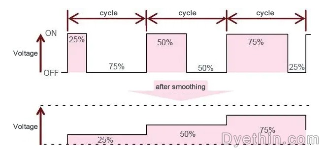
When the actual output voltage value is lower than the target voltage value, the ON time of the switching element is extended. Consequently, the output voltage will increase. In contrast, when the voltage exceeds the target value, the ON time of the control becomes shortened.
In this manner, the feedback control circuit constantly verifies the actual output voltage value and adjusts the ON/OFF time of the switching element based on the value to maintain the target output voltage value's stability.
What is mode for low load?
Light load mode refers to a method for maximizing output efficacy while consuming less output current. It is also referred to as surge mode in DC/DC converters and similar devices.
toggling AC/DC and DC/DC converters perform voltage chopping and capacitor smoothing via ON/OFF toggling to provide the desired output voltage value in a stable manner. Nonetheless, this switching generates transient leakage current (through current) during the ON/OFF cycle. In other terms, the greater the loss caused by leakage current and the lower the efficiency, the greater the ON/OFF cycles per unit time.
When the cycle is constant (PWM control), even if the ON/OFF time ratio varies, the number of ON/OFF cycles per unit time remains constant. Consequently, the quantity of self-dissipation is also constant, and the loss caused by this conversion leakage current under light loads will result in a reduction in efficiency. In the case of low current use, frequency modulation (PFM control) lengthens and slows the cycle, reducing the number of ON/OFF transitions per unit time and thereby minimizing losses. This method is known as low load mode.
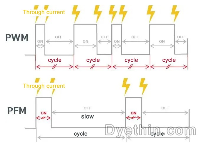
Using PWM and PFM based on the situation can further increase efficiency, such as using PWM control with a constant period when the load is heavy (using current) and using PFM control with a variable period when the load is light (no current).
PWM (Pulse Width Modulation): The frequency is constant, and the output control mode is derived from the input voltage via the ON switch.
PFM (Pulse Frequency Modulation) refers to the method of summoning the output component by fixing the ON time and varying the frequency (changing the OFF time). There is also a way to adjust the OFF time and alter the ON time.
The PFM method varies the frequency based on the quantity of output current and has a high level of efficiency, but intermittent noise may occur during switching. Eliminating this type of disturbance whose frequency cannot be determined is challenging. To eliminate the noise, it is simpler to employ a PWM procedure with a constant frequency.
Thus, PWM with minimal noise and PFM with high efficiency can complement one another. PWM is used when operating high loads with a high frequency (which results in more noise), while PFM is used when low loads use less current. Utilize only the finest to maximize efficiency.
2.DC/DC Converter
What are DC-to-DC converters?
A DC/DC converter is a component that converts direct current (DC) to direct current (DC), and specifically refers to a component that converts voltage using DC (direct current). ICs and other electronic components have distinct operating voltage ranges, so they must be converted to the appropriate voltages.
A converter that generates a lower voltage than the initial voltage is known as a "buck converter," while a converter that generates a higher voltage than the initial voltage is known as a "boost converter."
Name description
A DC/DC converter is a device that transforms direct current into direct current.
It is frequently referred to as a linear regulator or a toggling regulator, etc., based on the method of conversion.

Why is a DC/DC converter necessary?
To operate, plug-in electric devices require a "AC/DC converter" that converts 100V of alternating current (AC) to direct current (DC). Because the majority of semiconductor components can only operate under DC. The ICs installed on the circuit board of the entire machine each have their own inherent operating voltage ranges and voltage accuracy specifications. Providing power from a power source with an unstable voltage may result in anomalies, such as malfunction or deterioration of characteristics. Therefore, a "DC/DC converter" is required to convert and stabilize the requisite voltage.

A voltage regulator is a device that accomplishes voltage stabilization via a DC/DC converter.
Category of Power IC
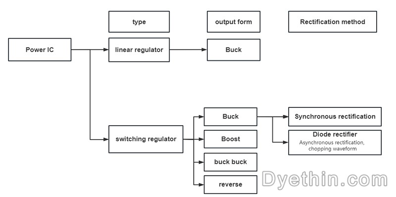
Linear regulators and switching regulators are the two most common varieties of power supply ICs.
Linear regulators can only step down an output voltage that is lower than the input voltage.
The switching regulator has degrees of freedom, and the four output categories are as follows:
The output voltage of the buck is less than the input voltage.
The output voltage of a boost circuit is greater than the input voltage
The buck-boost produces a constant output voltage regardless of the input voltage level.
Output negative voltage from positive voltage inversion
In addition, switching regulator rectification methods include synchronous rectification and asynchronous rectification (diode rectification).
Switching and Linear Regulators
A voltage regulator is a device that accomplishes voltage stabilization via a DC/DC converter.
Voltage regulators are divided into two categories based on the conversion method: linear regulators and switching regulators.
Linear regulator
It is termed a "linear regulator" because the relationship between input and output is linear during operation.
It is sometimes referred to as a "series regulator" because the control element between the input and output is connected in series.

The control element reduces the voltage, so the larger the difference in voltage between the input and output (the degree of voltage reduction), the greater the loss and the lower the efficiency. Consequently, it is appropriate for low-power power supplies.
Advantage:
basic circuit
minimal external elements
low din
Shortcoming:
limited performance
raging fever
Only Buck Convertible
modulating regulator
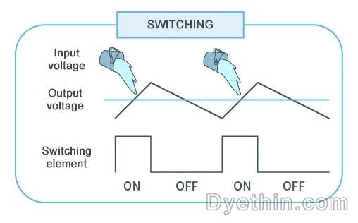
The switching element (MOSFET) is activated to provide power from the input to the output until the desired output voltage is reached.
After the output voltage reaches the specified value, the switching element is deactivated and input power consumption ceases.
By repeating this process at a rapid rate, the output voltage is adjusted to a predetermined value.

Advantage:
efficient
little fever
It can accomplish step-up/step-down and negative voltage conversions.
Shortcoming:
Many external components
Difficult to construct
loud commotion
How Linear Regulators Work
General connector configuration
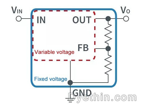
A linear regulator has three terminals: VIN (input), VO (output), and GND (ground).
FB (feedback port) is added to the variable output linear regulator for output voltage feedback.
The fixed voltage form is a voltage regulator with an integrated voltage-variable external resistor.
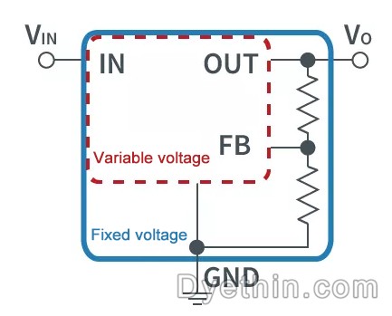
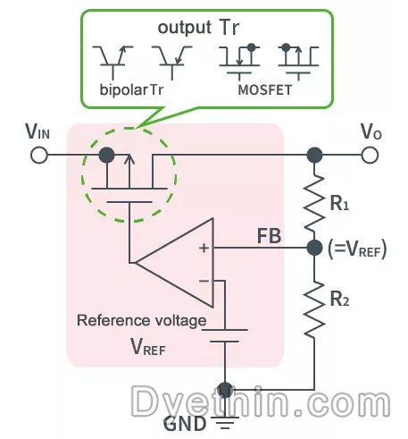
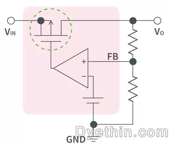
The schematic of the linear regulator's internal circuit is depicted in the figure below.
It operates on the same principle as an inverting amplifier circuit; the voltage of the non-inverting pin (FB) of the error amplifier is identical to the reference voltage (VREF); therefore, the output voltage value (VO) is determined by the resistance ratio of the two resistors (R1 and R2).
VO=[(R1+R2) / R2] x VREF
In the figure below, the output transistors are MOSFETs, but there are also products that use bipolar transistors.
Linear Regulator Category
categorized by function
By their function, linear regulators can be divided into two categories: positive voltage and negative voltage.
There are products that, depending on the circuit, do not require a positive power supply but do require a negative power supply.
If only the power supply on the positive side is available, voltages below ground potential cannot be handled, and the output input of the transistor cannot distribute voltage to a negative level. Connect the control transistor to the output line's negative terminal, thereby generating a negative voltage.
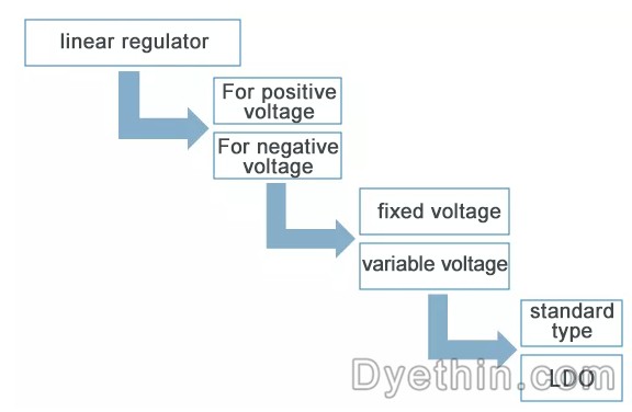
It can also be divided into two categories: types with fixed voltage and types with variable voltage. The fixed type has three ports, input, output, and GND, and an internal resistor for adjusting the output voltage.
When the variable type is a GND reference type, adding a feedback input increases the number of pins to four. Among the variants, there is also a GND-less floating operation type. In this instance, three needles are present.
The voltage fixed type and the voltage variable type can be further subdivided into standard type and LDO types.
Low Dropout, or LDO, is the abbreviation for a linear regulator that reduces the potential difference between input and output. The standard type has a minimum potential difference between the input and output of approximately 2V, whereas the LDO can be adjusted to less than 1V.
What is an LDO?
LDO is the abbreviation for minimal Dropout, and it refers to a linear regulator that can operate with a minimal input-to-output voltage difference.
Also known as a low-loss linear regulator and a low-saturation linear regulator.
There is no quantitative definition of the potential disparity between an LDO's input and output. In general, it refers to a voltage regulator whose minimal potential difference can be controlled to be less than 1V when functioning normally.
For an IC that requires a 3.3V power supply, for instance, since the standard type cannot produce a 5V to 3.3V power supply, an LDO with a low input-to-output potential difference is required.
This allows the LDO to specify a lower input voltage while maintaining the same output voltage as a standard regulator.
By operating at a low potential difference, energy loss can be minimized and designs such as heat dissipation can be eliminated.
Buck
A transistor is added between VIN and VO inside the linear regulator, and the voltage drop is the minimum potential difference between the input and output required for this transistor to operate reliably.
When the input-to-output voltage difference is less than the voltage drop, it is difficult for the transistor to maintain stable operation, and the output voltage will decrease.
Thus, in order for the linear regulator with LDO to function, the required minimum input voltage is set to (VO + voltage loss), which is the regulator's minimum operating voltage.
When the input voltage (VIN) is less than the minimum operating voltage, it is impossible to stabilize the output voltage.

Articles you may also like
Principles and applications of LDO
Working principle of field Mosfet transistor triode
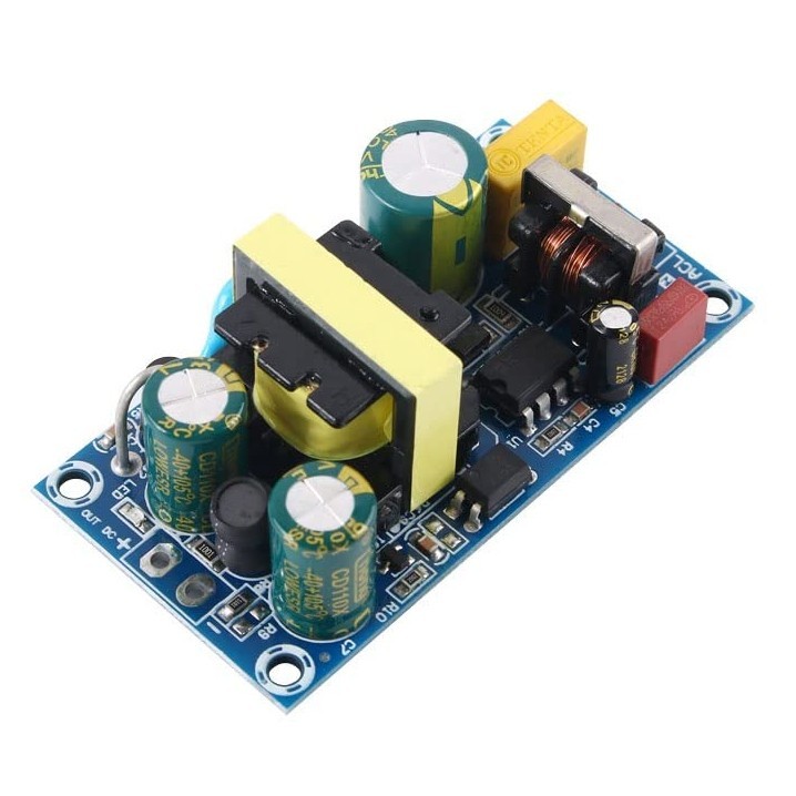
Basic knowledge and working principle of AC to DC converter
A Method for Optimizing the Gate Drive of SiC MOSFETs

-
-
-
-
microchip-technology
I2C, 2-Wire Serial Real-Time Clock IC with Battery-Backed SRAM and EEPROM
-
-
-
-

-