


- Ana Sayfa
- Featured Products
- Analog Devices
- AD8302 signal amplitude phase detection
AD8302 signal amplitude phase detection
AD8302 module


Introduction to AD8302
AD8302 is a monolithic integrated circuit introduced by ADI for measuring the amplitude and phase of RF/IF signals. It can simultaneously measure the amplitude ratio and phase difference between two input signals from low frequency to 2.7GHz. The device integrates two closely matched logarithmic detectors on a single chip, thereby minimizing error sources and associated temperature drift. The device's dynamic range can be extended to 60dB for amplitude measurements and 180 degrees for phase measurements.
Similar product
| AD8302ARU | AD8304ARUZ |
| AD8300AN | AD8309ARUZ |
| AD8309ARU | AD8306ARZ |
Chip Features
Comes with 1.8V reference output
Measures magnitude and phase from low frequency to 2.7GHz
Phase measurement 0-180°
Accurate typical to less than 1 degree
Accurate Phase Measurement Scale Factor of 10mV/Degree
Module pin
| pin name | Pin Description |
| VCC | Module power supply 2.7V - 5.5V |
| GND | power supply |
| AGND | Measuring output negative |
| VMAG | Amplitude output |
| VPHS | Amplitude output |
Working principle of AD8302
Internal block diagram

Working principle
The amplitude and phase measurement principle of AD8302 is mainly based on the logarithmic compression function of the logarithmic amplifier. His mathematical expression is:
VOUT=Vslplog( Vin / Vz )
The AD8302 measures the difference in the outputs of two identical log amps driven by signals with similar waveforms but different levels. Since the subtraction in the logarithmic domain corresponds to the division in the linear domain, the output becomes:
VMAG=Vslplog(VINA / VINB)
The output of the last stage of the logarithmic amplifier in the internal block diagram above is a finite signal that is completely within the dynamic range of the input signal. The two finite signals from the matched logarithmic amplifier drive an exclusive-or digital phase detector. With the method of zero point, the extracted phase difference has nothing to do with the original input signal level. The general expression for the phase output is:
VPHS=VΦ[Φ(VINA)-Φ(VINB)]
The above Vin is the input voltage;
Vz is the intercept;
Vslp is the slope;
VMAG is the amplitude discrimination output voltage;
VPHS is the amplitude discrimination output voltage;
VINA is the input signal A;
VINB is the input signal B;
VΦ is the phase frequency;
Φ is the relative phase of the signal;

Ideally, the amplitude ratio and phase difference between AD8302 input signal A and input signal B correspond to the curves of VMAG and VPHS.
experiment
wiring


phase identification
Signal input parameters: sine wave frequency 3M, amplitude 500mV change phase difference

The phase difference between INA and INB input signals is changed to 0°, and the voltage of VPHS measured by the multimeter is 1.804V
(In an ideal state, when the phase difference between INA and INB is 0°, the VPHS output voltage is 1.8V, and the ideal state cannot be achieved due to limited conditions)

The phase difference between INA and INB input signals is changed to 90°, and the voltage of VPHS measured by the multimeter is 0.91V
(In an ideal state, when the phase difference between INA and INB is 90°, the VPHS output voltage is 0.9V, and the ideal state cannot be achieved due to limited conditions)

The phase difference between INA and INB input signals is changed to 180°, and the voltage of VPHS measured by the multimeter is 0.0258V
(In an ideal state, when the phase difference between INA and INB is 0°, the output voltage of VPHS is 0V, and the ideal state cannot be achieved due to limited conditions)
Amplitude
The accuracy of the equipment in this experiment is limited, so only the experiment when the amplitude ratio is 0


In the experiment, INA and INB of AD8302 input two sine waves with an amplitude of 560mV respectively, and the VMAG measured by the multimeter is 0.93V.
(In an ideal state, the amplitude ratio of INA and INB is 0, and the output voltage of VMAG is 0.9V, and the ideal state cannot be achieved due to limited conditions)
The experiment is over.
Experiment summary
Personal experiments cannot rule out hardware errors and limited conditions. The experimental data is slightly different from the ideal curve in the manual. Chip differences will also make the actual measured data different from the ideal curve.
Articles you may also like
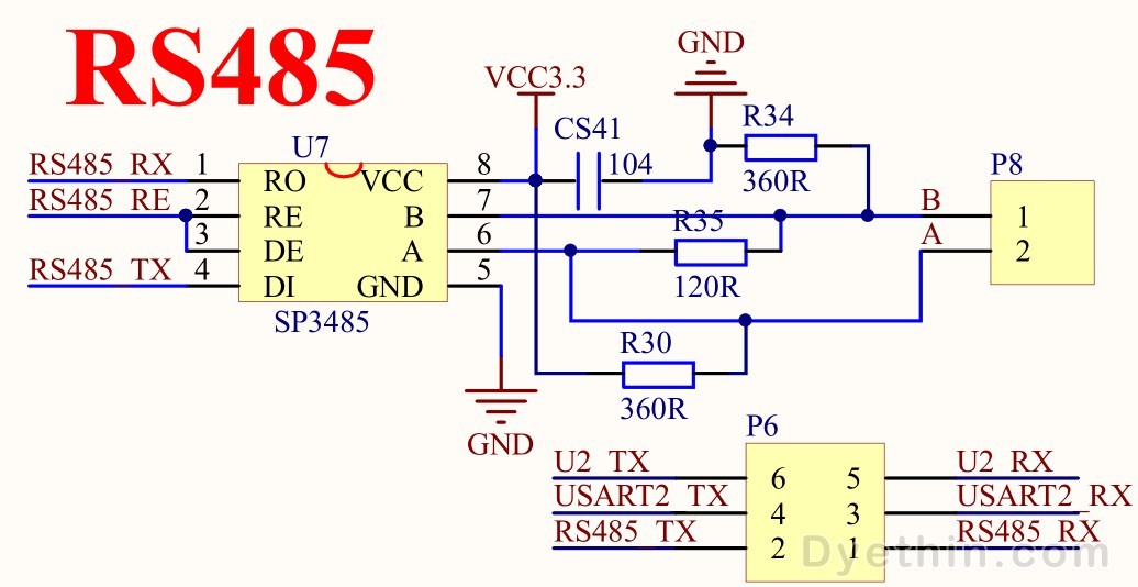
MAX485 is an RS 485/RS422 transceiver integrated circuit IC produced
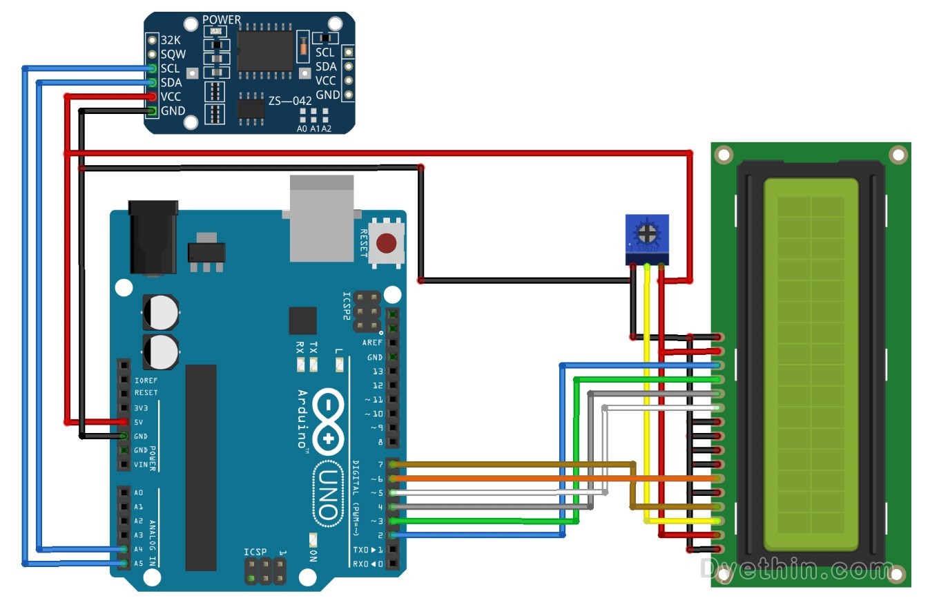
DS3231 RTC Module and Arduino Interface Build Digital Clock and DS3231 Datasheet
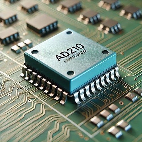
AD210 Precision Isolation Amplifier – Overview and Applications

-

-

-

-

texas-instruments
3-V to 5.5-V Multichannel RS-232 Line Driver and Receiver With ±15-kV ESD Protection 16SOIC
-

-

omron-automation-and-safety
General Purpose Relays SPDT (1 Form C) 10 A 220VAC
-

-

realtek
Integrated USB 2.0 Ethernet controller with WoL, EEE, OTP, and checksum offload.
-
