


- Home
- Featured Products
- Analog Devices
- DS3231 RTC Module and Arduino Interface Build Digital Clock and DS3231 Datasheet
DS3231 RTC Module and Arduino Interface Build Digital Clock and DS3231 Datasheet
What is the DS3231 clock IC?
DS3231 clock IC, also known as real-time clock RTC DS3231, is an integrated circuit with time counting function. It is mainly used to provide accurate time information in electronic devices, including seconds, minutes, hours, days, weeks, months, years, etc. Real time clock ICs typically contain components such as crystal oscillators, counters, and memory to ensure the accuracy and stability of time. Real time clock ICs are widely used in various fields, such as computers, communications, consumer electronics, industrial control, etc.

RTC DS3231 Features
From the RTC DS3231 Datasheet, it can be inferred that DS3231 has the following characteristics
● Highly Accurate RTC Completely Manages All Timekeeping Functions
• Real-Time Clock Counts Seconds, Minutes, Hours,Date of the Month, Month, Day of the Week, and Year, with Leap-Year Compensation Valid Up to 2100
• Accuracy ±2ppm from 0°C to +40°C
• Accuracy ±3.5ppm from -40°C to +85°C
• Digital Temp Sensor Output: ±3°C Accuracy
• Register for Aging Trim
• RST Output/Pushbutton Reset Debounce Input
• Two Time-of-Day Alarms
• Programmable Square-Wave Output Signal
● Simple Serial Interface Connects to Most Microcontrollers
• Fast (400kHz) I2C Interface
● Battery-Backup Input for Continuous Timekeeping
• Low Power Operation Extends Battery-Backup Run Time
• 3.3V Operation
● Operating Temperature Ranges: Commercial (0°C to +70°C) and Industrial (-40°C to +85°C)
● Underwriters Laboratories® (UL) Recognized
Application scope of DS3231
DS3231 is a high-precision I2C real-time clock device with internal temperature compensation and leap year compensation. Due to its high precision and wide temperature range characteristics, DS3231 is widely used in the following situations:
Servers
Telematics
Utility Power Meters
GPS
Time display and recording of electronic devices.
Time synchronization of industrial control systems.
The timestamp function of the data collection system.
The timing function of smart home devices.
Time synchronization and management of IoT devices.
DS3231 Typical Operating Circuit

The RTC DS3231 application data comes from the DS3231 Datasheet. For more applications, please refer to the DS3231 Datasheet
DS3231 Pinout

DS3231 typically has 6 or 8 pins, depending on the packaging form. These pins include:
VCC: Positive pole pin of power supply.
GND: Ground pin.
SCL: I2C serial clock pin.
SDA: I2C serial data pin.
SQW/OUT: Programmable square wave output pin.
RST: Reset pin (optional).
NC: No connection pins (optional).
DS3231 Pinout data from DS3231 Datasheet.
Usage of RTC DS3231
Firstly, connect the VCC pin of RTC DS3231 to the positive pole of the power supply and the GND pin to the ground terminal.
Connect the I2C interface of the microcontroller to the SCL and SDA pins of the RTC DS3231. Ensure that the microcontroller supports the I2C communication protocol.
As needed, connect the SQW/OUT pin to the interrupt input pin or other functional pins of the microcontroller.
Initialize the I2C interface of the microcontroller and configure it using the corresponding software library or driver program.
Read the time information of DS3231 IC through the I2C interface and perform corresponding processing or display.
As needed, a microcontroller can be used to set or calibrate the time of the DS3231 IC.
When using the battery backup function, ensure that the battery is correctly connected to the battery input pins of the DS3231 IC.
Tips for using DS3231 Circuit
To ensure the accuracy of time, it is recommended to use a high-quality crystal oscillator as the clock source for the DS3231 Circuit.
When using the battery backup function, it is recommended to choose button batteries with high energy density and ensure that they have a stable output voltage throughout the entire operating temperature range.
To avoid electromagnetic interference (EMI) issues, the DS3231 Circuit can be kept at a certain distance from other sensitive circuits or filtered using magnetic beads.
When using the programmable square wave output function, it is necessary to choose the appropriate output frequency and duty cycle according to the actual application requirements.
To ensure software compatibility and ease of use, vendor provided software libraries or third-party open-source libraries can be used for driver development and application implementation of DS3231 Circuit.
When designing a PCB, ensure that there is sufficient space around the IC for heat dissipation. At the same time, avoid placing thermal sensitive components near them.
In order to reduce costs and improve production efficiency, it is possible to consider using compatible alternative models for selection optimization. When selecting alternative models, it is necessary to fully consider whether their performance, packaging form, and cost meet the application requirements.
Advantages and disadvantages of RTC DS3231
Advantages:
High precision: The time accuracy of RTC DS3231 is usually within ± 0.432 seconds per day, suitable for various application scenarios that require high-precision time.
Wide temperature range: RTC DS3231 maintains high accuracy in the temperature range of -40 ° C to+85 ° C, suitable for various harsh environmental conditions.
I2C interface: The RTC DS3231 adopts the I2C serial communication protocol, which is compatible with most microcontrollers and facilitates system integration and expansion.
Programmable square wave output: The RTC DS3231 has a programmable square wave output function, which facilitates the implementation of various timing and triggering functions.
Battery backup: The RTC DS3231 supports battery backup function, ensuring the accuracy of time can still be maintained in case of power interruption.
Small package: The RTC DS3231 adopts a small package form, which is convenient for integration and application in various electronic devices.
Disadvantages:
High cost: Compared to other real-time clock ICs, the cost of DS3231 IC may be higher, which increases the overall cost of the product. To reduce costs, it is possible to consider using compatible alternative models for selection optimization. Meanwhile, optimizing production processes and procurement strategies can also help reduce costs.
Power supply requirements: The DS3231 IC requires a stable power supply to ensure its normal operation. When using in environments with high power fluctuations, attention should be paid to the stability of the power supply and filtering measures.
DS3231 RTC Module and Arduino Interface Build Digital Clock
In today's world, time is everything, and for specific electronic products, time is crucial; Just like us humans, they also need a way to record time. So how do electronic products do it?
The answer is DS3231, a real-time clock commonly known as RTC, which is a timing device built into an integrated circuit or IC. It is used for many time sensitive applications and devices, such as servers, GPS, and data recorders. Let's see what makes it tick.
DS3231 RTC Module Introduction
DS3231 is an I2C real-time clock (RTC) with a built-in temperature compensated crystal oscillator (TCXO) and a low-cost and exceptionally precise crystal. When the power supply to the module is interrupted, the device has a battery input and maintains precise timing. The long-term accuracy of this device has been improved due to the inclusion of a crystal oscillator. RTC tracks seconds, minutes, hours, days, dates, months, and years. For months with less than 31 days, the end of month date will be automatically modified, including leap year corrections. The clock has AM/PM indication and can operate in either 24-hour or 12 hour mode. Includes two programmable time alarms and one programmable square wave output. The I2C bidirectional bus is used for serial transmission of addresses and data.
DS3231 module pin arrangement
The DS3231 module has 6 pins, which are used to obtain data from the module and power the circuit board. The pin arrangement of DS3231 is as follows:


When we use an oscilloscope to detect the 32k pin of the DS3231 module, we will obtain a 32kHz signal from the internal oscillator of the IC.

DS3231 module composition
The key components of a typical DS3231 RTC module board are the DS3231 IC and AT24C32 EEPROM IC, which are used to store time and date data. Other components include power on LED, some resistors, capacitors, battery holder, and pins for connecting to the microcontroller.

DS3231 RTC Module
When the main power supply of the module stops, DS3231 contains battery input and maintains accurate time. The built-in power detection circuit continuously checks the status of the VCC to identify power outages and automatically switch to a backup power source. Therefore, even if there is a power outage, your MCU can still maintain time tracking. There is a CR2032 battery holder on the DS3231 RTC module. The battery holder for a 20mm 3V lithium button battery is located at the bottom of the circuit board. Any CR2032 battery can be used.
Charging capacity:
The design of this module is that it can charge the batteries installed on the module when powered externally. However, caution must be taken when using non rechargeable CR2032 batteries, as the module will also charge the battery. CR2032 is a non rechargeable 3V battery, but rechargeable batteries can charge up to 4.2V. To prevent the module from charging the CR2032 non rechargeable battery, the U4 (220R) resistor or D1 (1N4148) diode should be soldered.
DS3231 RTC Module schematic

DS3231 RTC Module schematic
Programming and setting the time for DS3231
Setting the time in the DS3231 module is quite simple. All you need to do is connect it to Arduino in the following configuration.

After completing the above connection, you need to connect Arduino UNO to your PC, open the Arduino IDE, and install the Arduino DS3231 Time Set Library. Open the Arduino IDE and select Library Manager from the menu bar. Now search for RTCLib and DS3231 and obtain the latest version, as shown in the following figure.

Code for setting time in DS3231
The code is very simple. It will set the time and then display it on the serial monitor.
rtc.adjust(DateTime(F(__DATE__),F(__TIME__)));
The RTC object sets the time in this line based on the time on your computer. It will change the current clock time of your system.
rtc.adjust(DateTime(2014, 1, 21, 3, 0, 0));
You can manually set the time in this row by passing the date time values to the function in the following order: year, month, day, hour, minute, and second. We will set the system's time in the following code. As a result, we commented out this line.
#include <RTClib.h>
#include <Wire.h>
RTC_DS3231 rtc;
char t[32];
void setup()
{
Serial.begin(9600);
Wire.begin();
rtc.begin();
rtc.adjust(DateTime(F(__DATE__),F(__TIME__)));
//rtc.adjust(DateTime(2019, 1, 21, 5, 0, 0));
}
void loop()
{
DateTime now = rtc.now();
sprintf(t, "%02d:%02d:%02d %02d/%02d/%02d", now.hour(), now.minute(), now.second(), now.day(), now.month(), now.year());
Serial.print(F("Date/Time: "));
Serial.println(t);
delay(1000);
}
Create a DIY Arduino digital clock using DS3231 and LCD
Arduino digital clock circuit diagram:

Connect the SCL of the RTC module to Arduino A5
Connect the SDA of the RTC module to Arduino A4
Connect VCC to 5V and GND to GND
Connect the RS of the LCD to pin 7 of Arduino
Connect the E of the LCD to pin 6 of Arduino
Connect the D7 of the LCD to pin 2 of the Arduino
Connect D6 of LCD to pin 3 of Arduino
Connect the D5 of the LCD to pin 4 of the Arduino
Connect the D4 of the LCD to pin 5 of Arduino
Connect VSS, K, RW, D0, D1, D2, D3 to GND
Connect VDD and A to 5V
Connect VO to the output pin of the potentiometer (used to control the contrast of the text)
Code for displaying time on LCD
We include the following header files in the code: Wire. h is used to communicate with the module using I2C, LiquidCrystal. h is used to display the time on the LCD display, and RTClib. h is used to set the display time and format it.
#include <Wire.h>
#include <LiquidCrystal.h>
#include <RTClib.h>
This line in the code specifies which pin of the LCD is connected to which pin of the Arduino.
LiquidCrystal lcd(7, 6, 5, 4, 3, 2); // (rs, e, d4, d5, d6, d7)
If the project starts due to a connection interruption, the code will print RTC Module not Present in the serial monitor.
if (! rtc.begin())
{
Serial.println(" RTC Module not Present");
while (1);
}
If the RTC loses power and the time in the module is incorrect, the code will automatically set the time in the module and retrieve the time from the computer clock. Therefore, please ensure that the clock on the PC is set to the correct time when setting the time.
if (rtc.lostPower())
{
Serial.println("RTC power failure, reset the time!");
rtc.adjust(DateTime(F(__DATE__), F(__TIME__)));
}
This part of the code sets the cursor on the LCD to 0 and prints the date in Date/Month/Year format.
void displayDate()
{
lcd.setCursor(0,0);
lcd.print("Date:");
lcd.print(now.day());
lcd.print('/');
lcd.print(now.month());
lcd.print('/');
lcd.print(now.year());
}
This part of the code sets the cursor to 1 and prints the time in Hour: Minute: Second format.
void displayTime()
{
lcd.setCursor(0,1);
lcd.print("Time:");
lcd.print(now.hour());
lcd.print(':');
lcd.print(now.minute());
lcd.print(':');
lcd.print(now.second());
lcd.print(" ");
}
After uploading the code, you will be able to see the date and time on the LCD screen.

DS3231 Datasheet And Module Code

DS3231 RTC Module complete code
Articles you may also like
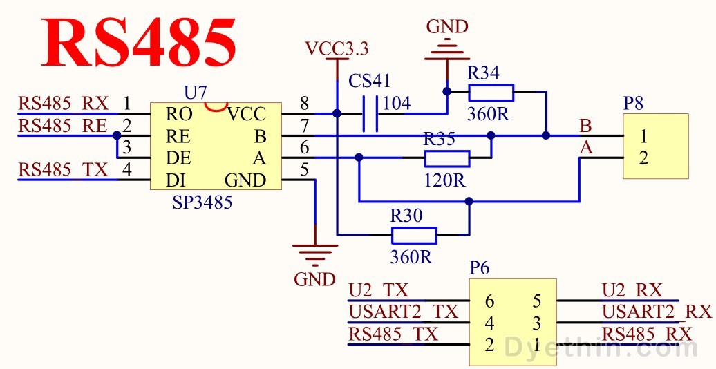
MAX485 is an RS 485/RS422 transceiver integrated circuit IC produced
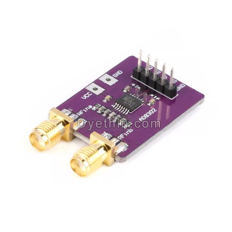
AD8302 signal amplitude phase detection
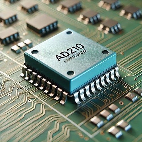
AD210 Precision Isolation Amplifier – Overview and Applications


