


- Accueil
- Blogs
- Semiconductor
- Silicon controlled rectifier (SCR) and switch control circuit explained
Silicon controlled rectifier (SCR) and switch control circuit explained
Silicon controlled rectifier(SCR) for some high-power switching control, also known as thyristor.In the automatic control system, the high-power driving device can be driven to achieve the purpose of controlling high-power equipment with low power. It is widely used in AC and DC motor speed control system.
What is silicon control rectifier(SCR)?
Silicon controlled rectifier (SCR) is a common semiconductor component that controls high voltage and power switches in various circuit boards. Thyristor is a 4-layer component composed of P-type and N-type materials to form NPNP or PNPN thyristor.
Construction of Silicon controlled rectifier(SCR)

The Silicon controlled rectifier(SCR) consists of 4 layers of semiconductor material, 3 PN junctions and 3 terminal devices.
Four-layer material: PNPN
Three knots: J1, J2, J3
Three terminals: Anode(A), Cathode(K), Gate(G)
Silicon controlled rectifier(SCR) symbol

The figure above shows the unidirectional Silicon controlled rectifier (SCR) symbols, consisting of which terminals are A (Anode), K (Cathode), G (Gate), the arrow indicates the direction of the diode circuit.
How does Silicon controlled rectifier(SCR) work?
Silicon controlled rectifier(SCR) operating principle is based on a special four-layer structure and the introduction of a control pole, which makes it possible to control a larger anode current or voltage by adding a smaller current or voltage to the control pole.
The conduction of the Silicon controlled rectifier(SCR) depends mainly on the positive voltage applied between the anode and cathode, and the positive trigger signal applied between the control pole and cathode. When these conditions are met, the SCR will conduct quickly, and its conduction state will remain until the anode current is reduced to a certain level or a reverse voltage is applied to the control pole to turn it off.
Silicon controlled rectifier(SCR) operating status
Ⅰ. Forward blocking (Disabled)

In this operating mode, the Silicon controlled rectifier(SCR) rectifier is connected so that the anode terminal is positive in relation to the cathode terminal and the gate terminal stays open, as illustrated in the picture below. As a result, a positive (+ve) voltage is applied to the anode (A) and a negative voltage to the cathode (K), while no pulse is applied to the gate connection, allowing it to remain open. When a voltage is given to the Silicon controlled rectifier(SCR) in this state, nodes J1 and J3 are forward biased, while node J2 becomes reverse biased.
Because of the reverse bias voltage at junction J2, the breadth of the junction depletion zone increases dramatically, making it an impediment to electrical conduction between J1 and J3. As a result, the majority of the applied current does not pass through the Silicon controlled rectifier(SCR); but, a tiny amount of leakage current can pass from J1 to J3.
If the voltage applied to the Silicon controlled rectifier(SCR) rises to the breakdown voltage (VB), the junction J2 is depleted due to avalanche breakdown produced by high energy minority carriers. Once the avalanche breakdown occurs at junction J2, current begins to flow through the SCR; nevertheless, the Silicon controlled rectifier(SCR) has a very high resistance to current flow below its breakdown voltage (VB). As a result, it functions as an off switch and is known as the off state. As a result, no current will pass through the Silicon controlled rectifier(SCR), even if it is positively biased.
Ⅱ. Forward Conducting (On state)

The Silicon controlled rectifier(SCR) conducts current using either of the following methods:
Increase the forward bias voltage, or the voltage applied between the anode and cathode terminals, to exceed the SCR's breakdown voltage (V B).
Apply a positive voltage (VG) to the gate terminals.
If the applied forward bias voltage exceeds the SCR's breakdown voltage, avalanche breakdown occurs at junction J2. As a result, the Silicon controlled rectifier(SCR)enters full conduction mode and functions as a closed switch, enabling current to pass through it. The latching current (IL) is the current generated when the SCR switches from forward blocking to forward conduction mode.
For low-voltage applications, gate forward bias is favored because the Silicon controlled rectifier(SCR) can begin conducting with only a little positive voltage (V G) applied to the gate terminals, as shown in the figure below.
NOTE: The Silicon controlled rectifier(SCR) is only operational in the forward conduction mode. Furthermore, activating the Silicon controlled rectifier(SCR) by raising the forward bias voltage applied between the anode and cathode is restricted to specific applications. This procedure will eventually limit the lifespan of the Silicon controlled rectifier(SCR).
Ⅲ. Reverse Blocking (Disabled)

In the reverse blocking mode, a positive voltage is applied to the cathode (negative) and a negative voltage is applied to the anode (positive), but no pulse is applied to the gate terminal, which stays open, as illustrated in the circuit diagram below. In this state, nodes J1 and J3 become reverse biased, whereas J2 becomes forward biased.
The reverse bias voltage between nodes J1 and J3 causes the Silicon controlled rectifier(SCR) to enter the reverse blocking zone, preventing current from flowing through the Silicon controlled rectifier(SCR) circuit, which functions as a disconnect switch. However, due to the drift of the charge carriers in the forward-biased J2 junction, a little amount of leakage current will flow, but insufficient to switch the Silicon controlled rectifier(SCR) on; thus, the Silicon controlled rectifier(SCR) will remain off.
How to test silicon controlled rectifier?
Motor control with Silicon controlled rectifier(SCR)
Controlling DC Motors

Consider the image above, which shows how an Silicon controlled rectifier(SCR) is used to control the speed of a DC motor. that a direct current (DC) motor has a magnetic field and an armature winding. The speed of a DC motor can be regulated by adjusting the voltage delivered to its armature.
AC power is provided to a transformer's primary and secondary windings, and two SCRs are connected in parallel, as illustrated in the figure. The outputs of these SCRs power the DC motor. The excitation winding is connected by a diode, which delivers unregulated DC power to it.
SCR1 is forward biased during the positive half of the input cycle and begins to conduct when the gate receives a trigger pulse. As a result, load current passes through SCR1 to the DC motor. During the input's negative half-cycle, SCR 2 is positively biased and SCR 1 is reverse biased, therefore SCR1 is turned off.
When SCR2 receives a gate trigger, it begins to conduct. trigger input of each SCR, the average output of the DC motor changes, allowing you to alter its speed.
Controlling AC Motors

The speed of an AC induction motor is regulated by changing the stator voltage applied to it. The diagram above depicts the connection of SCRs for adjusting the voltage applied to the stator of an induction motor.
Each phase has two SCRs connected in reverse parallel, one for the positive peak and the other for the negative peak. Thus, six Silicon controlled rectifier(SCR) setups are used to provide variable power.
This set of thyristors supplies the three-phase induction motor with three-phase alternating current power. When these thyristors are triggered by a delayed pulse, the average voltage provided to the induction motor fluctuates, causing the speed to vary.
Commonly used high power Silicon controlled rectifier(SCR)
2N6508: 800V withstand voltage and 25A current capacity, the more used items are industrial motor control and power regulation.
TYN612: 600V withstand voltage and 12A current capacity, the main application items are power supply equipment, dimmer and heating control.
SKKT 57/16 E: module high-power thyristor, 1600V withstand voltage and 57A current capacity, commonly used in large-scale heavy industrial equipment.
MCR72-6: 600V withstand voltage and 16A current capacity, the main application scenarios voltage protection circuit and power supply regulation.
K30H603: 1600V withstand voltage and 30A current capacity, mainly used in high voltage power projects.
ST330C14: 1400V withstand voltage and 330A current capacity, commonly used in high power conversion and industrial control.
TIC126M: 400V withstand voltage and 12A SCR, used for dimmers and power control.
Summary
Silicon controlled rectifier(SCR) are electronic parts that are used in most industrial or commercial electronic products to provide power control and switching functions. Learning about Silicon controlled rectifier(SCR) symbols, common circuit applications, test methods, and high power variants is important for designing hardware solutions.
 and switch control circuit explained)
FAQs
Articles you may also like
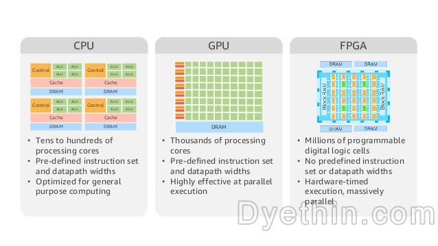
Characteristics of CPU, GPU, and FPGA
The difference between RAM ROM FLASH

Accurately measure resistor value using ADC
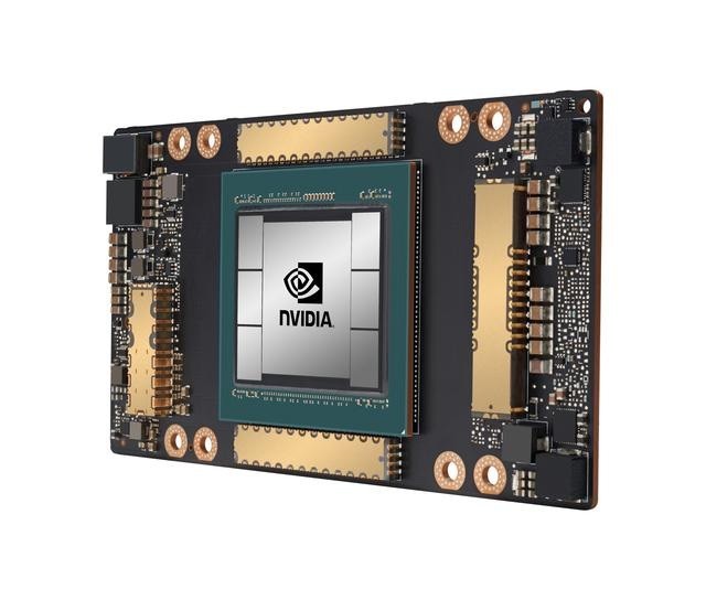
What is a GPU? What is the relationship between GPU and graphics card?

-

-

-

-

-

-

aeroflex-macom-technology-solutions
-

-

-
