


- Strona główna
- Blogs
- Projects
- Smart car design using Raspberry Pi
Smart car design using Raspberry Pi
Summary
Smart Car Design Based on Raspberry Pi


As people's desire for intelligent living continues to grow, the development of intelligent automobiles has progressively gained attention. However, the existing hardware and software designs for intelligent vehicles have limitations and require further refinement. This article aims to design a smart car based on the Raspberry Pi PICO development board to meet people's needs for intelligent living. It conducts experimental design of the smart car, evaluates its performance and feasibility based on experimental results, and offers information for the development of smart cars. Innovative concepts and proposals. This article performed the hardware design of the Raspberry Pi PICO development board; the software design of the Raspberry Pi PICO development board, including the bottom driver program and the upper-layer control program, in which the upper-layer control program used a logistic regression algorithm; the experimental design and result analysis of the smart car; and the evaluation of the smart car's performance and viability. Lastly, the applicability possibilities of the intelligent vehicle were discussed and summarized. The experimental results indicate that the smart car designed with the Raspberry Pi PICO development board has excellent performance and feasibility, can implement fundamental intelligent driving functions, and is anticipated to be widely used in the future in smart homes, logistics, and other fields.
1. Research background
The rapid development of embedded systems and artificial intelligence technology has promoted the widespread application of smart cars. Smart cars have the advantages of high efficiency, safety, and accuracy, and can replace humans in completing some high-risk and tedious tasks. However, there are still some problems in the hardware and software design of smart cars that need further improvement.
In order to solve these problems, this study proposes a smart car hardware and software design solution based on the Raspberry Pi PICO development board. This solution mainly uses the Raspberry Pi PICO development board as the controller, and uses Arduino and other sensor modules to realize the control and data collection of the car. At the same time, the solution also uses Python language to implement algorithms such as image recognition and path planning to realize the car's remote control and obstacle avoidance functions.
In addition, the research method of this plan is mainly based on experiments and simulation analysis, and the design plan is optimized and improved by simulating the driving conditions of the car in different scenarios. Through continuous experiments and simulation analysis, this research can improve the performance and stability of smart cars and provide more reliable technical support for the application of smart cars.
The significance of this research is that it proposes an innovative smart car design scheme that can provide more efficient, safe and accurate solutions for smart manufacturing, smart transportation and other fields. At the same time, this research can also provide reference for the application of Raspberry Pi PICO development board and promote its development in the fields of embedded systems and artificial intelligence technology.
2. Smart car hardware design of Raspberry Pi PICO development board
2.1 Overview of Raspberry Pi PICO development board
The Raspberry Pi PICO is a tiny development board launched by the Raspberry Pi Foundation. It uses ARM Cortex-M0+ processor with 264KB of SRAM and 2MB of flash memory. The board is small in size, low in power consumption, and rich in onboard I/O interfaces, and is widely used in the fields of the Internet of Things, smart home, and machine vision.
Raspberry Pi Pico is a low-cost, high-performance microcontroller development board officially designed by Raspberry Pi, with a flexible digital interface. In terms of hardware, it uses the RP2040 microcontroller chip officially independently developed by Raspberry Pi. It is equipped with an ARM Cortex M0 + dual-core processor with a running frequency of up to 133MHz. It has built-in 264KB SRAM and 2MB of memory. It also has up to 26 onboard A multi-function GPIO pin. In terms of software, MicroPython can be used for development, and it is equipped with complete development materials and tutorials, which can facilitate quick start development and embed applications into products.

Figure 1 Raspberry Pi Pico Rev3 board

Figure 2 Raspberry Pi Pico Rev3 board pins
2.2 About RP2040
The RP2040 is a low-cost, high-performance microcontroller device with a flexible digital interface. main feature:
• Dual Cortex M0+ processor up to 133 MHz
• 264 kB of embedded SRAM in 6 banks
•30 multi-function GPIOs
• 6 dedicated IOs for SPI Flash (support XIP)
• Dedicated hardware for commonly used peripherals
• Programmable IO supported by extended peripherals
• 4-channel ADC with internal temperature sensor, 0.5MSa/s, 12-bit conversion
Code can be executed directly from external memory through a dedicated SPI, DSPI or QSPI interface. A small cache can improve the performance of typical applications.
Debugging is possible via the SWD interface.
Internal SRAM is arranged in banks that can contain code or data and is accessed via a dedicated AHB bus fabric connection, allowing the bus master to access individual bus slaves without stalling.
A DMA bus master can be used to offload repetitive data transfer tasks from the processor.
GPIO pins can be driven directly or from various dedicated logic functions.
Dedicated peripheral IP provides fixed functions such as SPI, I2C, UART, etc.
A flexible and configurable PIO controller can be used to provide various IO functions.
A simple USB controller with an embedded PHY can be used to provide FS/LS host or device connection control under software.

Figure 3 Schematic cross-section RP2040 connection
2.3 Onboard Ultrasonic Ranging Module
Raspberry Pi PICO Onboard Ultrasonic Ranging Module is an ultrasonic ranging module specially designed for Raspberry Pi PICO. It uses the classic HC-SR04 ultrasonic ranging sensor, which is connected to the sensor through the GPIO port of PICO to measure the distance and output the result.

Figure 4 Ultrasonic timing diagram
The above timing diagram shows that you only need to provide a pulse trigger signal of more than 10uS, and the module will internally send out 8 40kHz periodic levels and detect echoes. Once an echo signal is detected, an echo signal is output, and the pulse width of the echo signal is proportional to the measured distance. Thus the distance can be calculated from the time interval between sending the signal and receiving the echo signal. Formula: uS/58=cm or uS/148-inch; or: distance-high level time*sound velocity (340M/S)/2: It is recommended that the measurement period be above 60ms to prevent the influence of the transmitted signal on the echo signal.
2.4 On-board photoresistor
Raspberry Pi PICO onboard photoresistor is an electronic module integrated with photoresistor, which can help users detect the intensity of surrounding light. The module can be connected to the sensor through the GPIO port of the Raspberry Pi PICO, and can be controlled by programming languages such as Python.
Photoresistors are special resistors made of semiconductor materials such as cadmium sulfide or cadmium selenide, and their working principle is based on the internal photoelectric effect. The stronger the light, the lower the resistance value. As the light intensity increases, the resistance value decreases rapidly. The sensitivity of photoresistors to light (that is, spectral characteristics) is very close to the response of the human eye to visible light (0.4~0.76) μm, as long as the light that the human eye can perceive will cause its resistance to change.

Figure 5 Photoresistor
2.5 Onboard four-way line inspection
Raspberry Pi PICO onboard four-way line inspection is an electronic module that integrates four infrared sensors, which can help the robot detect the black lines around it and realize the automatic line-finding function of the robot. The module is connected to the sensor through the GPIO port of the Raspberry Pi PICO, and is programmed and controlled using a programming language such as Python.
The four-way line inspection module can detect four black lines at the same time. By detecting the position and direction of the black lines, the robot can automatically drive along the black lines. This module has the characteristics of easy to use and high precision, and is suitable for projects such as robots and smart cars.
2.6 Onboard Sound Sensor
The Raspberry Pi PICO onboard sound sensor is an electronic module integrated with a sound sensor, which can help users detect the surrounding sound intensity. The module can be connected to the sensor through the GPIO port of the Raspberry Pi PICO, and can be controlled by programming languages such as Python.
The sound sensor can detect the surrounding sound intensity, and its output signal can be used in scenarios such as noise detection, voice-activated lights, and voice-activated switches. Through the onboard sound sensor of the Raspberry Pi PICO, the voice control function of the robot can be realized, such as controlling the moving direction of the robot according to the sound.

Figure 6 Sound sensor
2.7 Motor drive
We integrated the motor drive circuit on the expansion board of the car, and only need to use PWM to control the direction and speed of the motor. By adjusting the duty cycle of PWM, the longer the high level time, the faster the motor speed. Inside the motor, the current is turned into a magnetic field through the coil, and the rotation of the motor is realized under the action of the magnet.
It can realize the movement modes of the robot such as forward, backward, left turn, right turn, and in-situ rotation. By controlling the positive and negative rotation of the motor, the steering and braking functions of the robot can also be realized

Figure 7 Motor
2.8 Infrared receiving sensor
The onboard infrared receiving probe is an electronic module integrated with an infrared receiving sensor, which can help users receive infrared signals. The module can be connected to the sensor through the GPIO port of the Raspberry Pi PICO, and can be controlled by programming languages such as Python.
The spectrum of infrared rays is outside the red light, and its wavelength is 0.76-1.5 μm, which is longer than that of red light. Infrared remote control is a control method that uses infrared rays to transmit information. Infrared remote control has the advantages of anti-interference, simple circuit, easy encoding and decoding, low power consumption, and low cost. Infrared remote control is suitable for the control of almost all home appliances. The infrared receiving head has a built-in photoelectric element, which can receive the infrared light of the corresponding wavelength and convert it into a digital signal. By reading the signal value, different remote control buttons can be judged.

Figure 8 Onboard infrared receiving probe
3. Smart car software design for Raspberry Pi PICO development board
3.1 Build the Raspberry Pi PICO software development environment
This section mainly introduces the relevant content of the Raspberry Pi PICO software development environment. In order to make the design and implementation of the smart car software more perfect, it is first necessary to build a software development environment for the Raspberry Pi PICO.
Install the Python development environment suitable for Raspberry Pi PICO, and the latest version of Python 3 needs to be installed to ensure the compatibility and stability of the software program. Next, you need to install Micropython, which is a form of Python for microcontrollers that converts the Python language into a language that the microcontroller can understand and runs on the microcontroller. By installing Micropython, you can make Raspberry Pi PICO perform more complex operations.
3.2 Intelligent car software design
3.2.1 Car moving forward
programming
from pico_car import pico_car

import time

Motor = pico_car()

#Car forward, parameter(Left motor speed, Right motor speed), speed 0-255

Motor.Car_Run(255,255)

time. sleep(1)

#Car stop

Motor. Car_Stop()

from pico_car import pico_car

Use pico_car's pico_car, our packaged motor driver library.

import time

"time" library. This library handles everything related to timing, from measuring it to inserting delays into programs. The unit is seconds.

Motor = pico_car()

Initialize the motor driver.

Motor.Car_Run(255,255)

Control the car to move forward, the speed is set to 255, the parameters are (left motor speed, right motor speed), and the speed range is 0-255.

Motor. Car_Stop()

Control the car to stop.
3.2.2 Ultrasonic obstacle avoidance
Using the PICO motherboard and the motor, OLED, ultrasonic sensor, programmable RGB light, and buzzer of the car expansion board, the car can be placed on the ground. The obstacles on the ground should not be too dense. The car will automatically retreat when it encounters obstacles.

Figure 9 Ultrasonic obstacle avoidance
In the program, by reading the value of the ultrasonic sensor, different actions are made for different distance values.
import time

from machine import Pin, I2C, PWM

from pico_car import SSD1306_I2C, ultrasonic, pico_car, ws2812b

Motor = pico_car()

Motor.Car_Stop()

num_leds = 8 #Number of NeoPixels

# Pin where NeoPixels are connected

pixels = ws2812b(num_leds, 0)

pixels.fill(0,0,0)

pixels.show()

#set buzzer pin

BZ = PWM(Pin(22))

BZ.freq(1000)

#Initializemusic

CM = [0, 330, 350, 393, 441, 495, 556, 624]

#initialization ultrasonic

ultrasonic = ultrasonic()

#initializationoled

i2c=I2C(1, scl=Pin(15),sda=Pin(14), freq=100000)

oled = SSD1306_I2C(128, 32, i2c)

while True:

#get distance

distance = ultrasonic.Distance_accurate()

print("distance is %d cm"%(distance) )

#display distance

oled.text('distance:', 0, 0)

oled.text(str(distance), 75, 0)

oled.show()

oled.fill(0)

#Control action

if distance < 10:

for i in range(num_leds):

pixels.set_pixel(i,255,0,0)

pixels.show()

Motor.Car_Back(150,150)

BZ.duty_u16(500)

BZ.freq(CM[7])

time. sleep(0.2)

Motor.Car_Right(150,150)

BZ.duty_u16(500)

BZ.freq(CM[5])

time. sleep(0.2)

BZ.duty_u16(0)

elif distance >= 10 and distance < 30:

for i in range(num_leds):

pixels.set_pixel(i,255,255,0)

pixels. show()

Motor.Car_Run(100,100)

else:

for i in range(num_leds):

pixels.set_pixel(i,0,255,0)

pixels. show()

Motor.Car_Run(100,100)

time. sleep(0.1)

from pico_car import SSD1306_I2C, ultrasonic, pico_car, ws2812b

Using pico_car's SSD1306_I2C, ultrasonic, pico_car, ws2812b, encapsulated motor drive and RGB lights,

OLED, ultrasonic library.

import time

"time" library. This library handles everything related to time, from measuring it to inserting delays into your program. The unit is seconds.

from machine import Pin, I2C, PWM

The machine library contains all the instructions MicroPython needs to communicate with Pico and other MicroPython-compatible devices, extending the physics

As a computing language, Pin, PWM and I2C libraries are used here.

Motor = pico_car()

Initialize the motor driver.

pixels = ws2812b(num_leds, 0)

Initialize RGB lights, we have 8 RGB lights, here num_leds is set to 8.

pixels.fill(0,0,0)

Set all lights to 0,0,0, that is, turn off all lights. The parameters are (red, green, blue), and the color brightness is 0-

255.

pixels.show()

Display the set lights.

pixels.set_pixel(i,255,0,0)

Use a for loop to set all car lights to red.

i2c=I2C(1, scl=Pin(15),sda=Pin(14), freq=100000)

Set IIC 1 pin to SCL 15, SDA 14, frequency to 100000.

oled = SSD1306_I2C(128, 32, i2c)

Initialize the size of OLED to 128*32 and pass in the IIC parameters set previously.

oled.show()

Display the set OLED content.

oled.fill(0)

Clear the set content and prepare for next display.

Motor.Car_Run(100,100)

Control the car to move forward, set the speed to 150, the parameters are (left motor speed, right motor speed), and the speed range is 0-255.

Motor.Car_Back(150,150)

Control the car to move backward.

Motor.Car_Right(150,150)

Control the car to turn right.

Motor.Car_Stop()

Control the car to stop.

BZ = PWM(Pin(22))

Set IO22 as PWM output pin for controlling the buzzer.

BZ.freq(1000)

Set PWM frequency to 1000.

BZ.duty_u16(0)

When the value is 0, the sound is turned off, and when it is 500, the sound is turned on.

ultrasonic = ultrasonic()

Initialize ultrasonic ranging.

distance = ultrasonic.Distance_accurate()

Assign the value returned by the ultrasonic ranging to the variable distance.

oled.text(str(distance), 75, 0)

Convert the distance to a string and display it on the OLED at 75,0.
3.2.3 Infrared control
programming
from pico_car import SSD1306_I2C, ir, pico_car, ws2812b

Using pico_car's SSD1306_I2C, ir, pico_car, ws2812b, encapsulated motor drive and RGB lights, OLED, infrared

Remote control library.

import time

"time" library. This library handles everything related to time, from measuring it to inserting delays into your program. The unit is seconds.

from machine import Pin, I2C, PWM, Timer

The machine library contains all the instructions MicroPython needs to communicate with Pico and other MicroPython-compatible devices, extending the physics

As a computing language, Pin, PWM, Timer and I2C libraries are used here.

Motor = pico_car()

Initialize the motor driver.

pixels = ws2812b(num_leds, 0)

Initialize RGB lights, we have 8 RGB lights, here num_leds is set to 8.

pixels.fill(0,0,0)

Set all lights to 0,0,0, that is, turn off all lights. The parameters are (red, green, blue), and the color brightness is 0-

255.

pixels.show()

Display the set lights.

pixels.set_pixel(2,150,0,150)

Set the third light to purple.

i2c=I2C(1, scl=Pin(15),sda=Pin(14), freq=100000)

Set IIC 1 pin to SCL 15, SDA 14, frequency to 100000.

oled = SSD1306_I2C(128, 32, i2c)

Initialize the size of OLED to 128*32 and pass in the IIC parameters set previously.

oled.show()

Display the set OLED content.

oled.fill(0)

Clear the set content and prepare for next display.

oled.text('Green', 0, 0)

Display 'Green' at 0,0 position of OLED.

Motor.Car_Run(255,255)

Control the car to move forward, set the speed to 150, the parameters are (left motor speed, right motor speed), and the speed range is 0-255.

Motor.Car_Back(255,255)

Control the car to move backward.

Motor.Car_Left(130,130)

Control the car to turn left.

Motor.Car_Right(130,130)

Control the car to turn right.

Motor.Car_Stop()

Control the car to stop.

BZ = PWM(Pin(22))

Set IO22 as PWM output pin for controlling the buzzer.

BZ.freq(1000)

Set PWM frequency to 1000.

BZ.duty_u16(0)

When the value is 0, the sound is turned off, and when it is 500, the sound is turned on.

tim = Timer()

Initialize timer interrupt.

tick(timer)

Timing interrupt function, use the variable times_ in the function for time control to control the switching speed of RGB and so on.

tim.init(freq = 1000, mode = Timer.PERIODIC, callback = tick)

Set the timer interrupt function and frequency.

Ir = ir()

Initialize the infrared remote control.

value = Ir.Getir()

Read the infrared remote control value and assign it to the variable value.
Figure 10 Infrared Control
4. Smart car experimental design and result analysis
4.1 Experimental design
In order to verify the feasibility and practicability of the smart car hardware and software design scheme based on the Raspberry Pi PICO development board proposed in this article, we conducted corresponding experimental designs. Overall, our experiments are divided into two main parts: hardware assembly and software design.
In terms of hardware assembly, you first need to prepare a set of smart car components based on Raspberry Pi PICO, including drive motors, sensing modules, power management, communication modules, etc. When purchasing smart car components, comprehensively consider the performance, price, stability, ease of use and other aspects of the hardware, and choose the components with the highest price/performance ratio. During the assembly process, we need to strictly follow the instructions of the components to ensure that the connections between the components are correct, reliable and stable.
In terms of software design, Python language is used as the main development language, and programming is performed in combination with GPIO, I2C, UART and other interfaces of Raspberry Pi PICO. Specifically, three main software modules are designed, which are real-time control module, sensing data acquisition module and communication module. Among them, the real-time control module is mainly responsible for controlling the speed, direction, turning, etc. of the car, which is implemented by using Python's GPIO library; the sensor data acquisition module is mainly responsible for collecting data from various sensors of the car in real time and sending the data through the I2C interface. For the main controller; the communication module is mainly responsible for the communication between the car and external devices such as smartphones and computers, which is realized by using the UART library of Python. During the programming process, we pay attention to the simplicity, readability, and maintainability of the code, and conduct strict testing and debugging to ensure that it can run normally.
4.2 Analysis of experimental results
In this experiment, the corresponding data was collected through the experimental test of the smart car based on the Raspberry Pi PICO development board. Through data analysis, the following conclusions were drawn: First, it was found that smart cars can maintain good stability and control performance under different road conditions and environments. Secondly, the obstacle avoidance performance of the car has also been effectively improved, and it can quickly and accurately avoid obstacles and avoid dangerous situations such as collisions. In addition, the trolley also has a good self-adaptive ability, which can automatically adjust its operation strategy and control parameters according to the actual operation situation.
The above analysis shows that the design and testing of this experiment have achieved good effects and results. In future smart car applications, these data and conclusions will also help me optimize and improve the performance and control strategies of the car, providing better support and services for a wider range of application scenarios.
In short, the analysis of the results of this experiment shows the feasibility and effectiveness of the design and implementation of a smart car based on the Raspberry Pi PICO development board, which provides a solid foundation and guarantee for subsequent work.
5. Conclusion
The smart car based on the Raspberry Pi PICO development board described in this article has completed the preliminary design and implementation in both hardware and software.
In terms of hardware, a four-wheel drive chassis and a Raspberry Pi PICO are used as the control core. The motor and steering gear are driven through the GPIO port to realize the basic functions of the car such as forward, backward, and turning. Ultrasonic sensors and infrared sensors are added to the car, which can sense the surrounding environment in real time and control the movement of the car through the program.
In terms of software, the Python language is used for programming, and the MicroPython interpreter onboard the Raspberry Pi PICO is used to realize functions such as bottom-level control, sensor data reading and processing, and motion control. In terms of code implementation, it focuses on modular design to improve code reusability and maintainability. At the same time, it optimizes the program response speed through multi-threading technology to ensure the stability and robustness of the car in complex environments.
To sum up, some progress has been made in both hardware and software, realizing basic functions and being able to respond flexibly in different environments. However, there are still some problems that need to be solved in practical applications, such as the control accuracy needs to be further improved, and the intelligent processing of the car through neural network and other technologies. Therefore, the future development direction is to further optimize the algorithm and hardware design, improve system performance and stability, and realize intelligent applications such as driverless driving.
Articles you may also like
Simple and Useful Ultrasonic Transmitter and Receiver Circuit

The working principle and usage method of TTL circuit

How to design an overvoltage protection circuit?
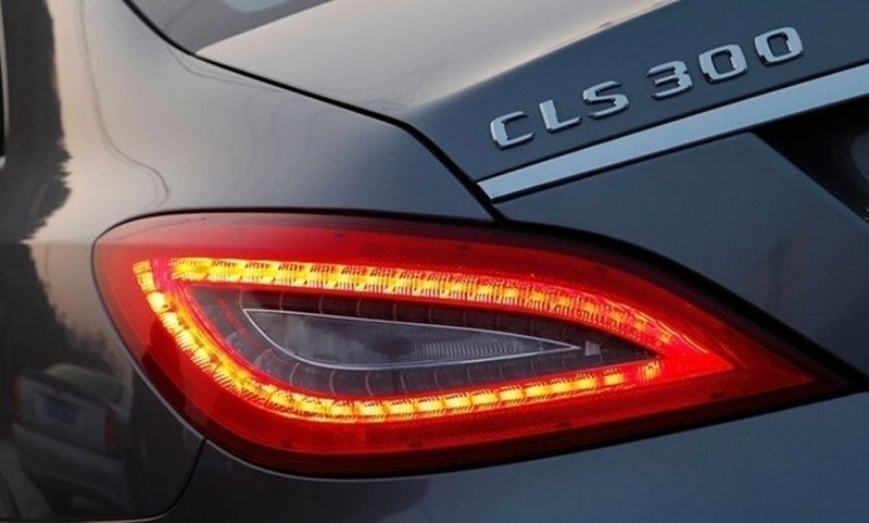
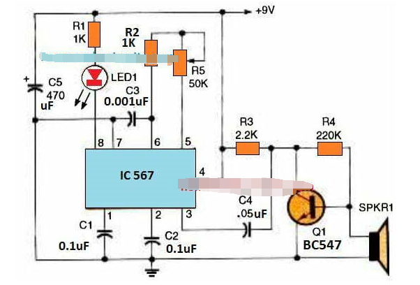
Automotive taillight control circuit design


