













- Home
- Blogs
- Power management
- Brief Analysis of Capacitance in AC Circuit
Brief Analysis of Capacitance in AC Circuit
When DC supply voltage is applied to the capacitor, it gradually charges until it reaches the fully charged state. At this juncture, the capacitor's charging voltage is equal to the power supply voltage.
As long as a voltage is applied, the capacitor functions as an energy source. When capacitors are completely charged, they prevent the passage of current (i). Current in a circuit is proportional to the rate of change of the voltage applied to the circuit and to the quantity of charge in the capacitor plates.
Consequently, i = dQ/dt = C dV(t)/dt.
If an AC mains voltage is applied to the capacitor circuit, the capacitor will continuously charge and discharge at the frequency of the mains voltage. In an AC circuit, the capacitance of a capacitor is dependent upon the frequency of the supply voltage applied across it. In an AC circuit, when the supply voltage varies continuously with respect to time, a capacitor allows current to travel.
AC capacitor circuit
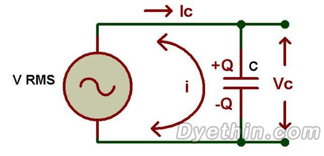
In the circuit shown above, the capacitor is connected directly to the AC line voltage. In this case, the capacitor is continuously charged and discharged in accordance with the varying value of the AC mains voltage as the value of the AC mains voltage continues to increase and decrease. Current in a circuit is proportional to the rate of change of the applied voltage, as is common knowledge.
If the supply voltage crosses from a positive half cycle to a negative half cycle and vice versa, the charging current has a high value. In a sine wave signal, this is between 00 and 1800. When the supply voltage of a sine wave exceeds its maximum or minimum peak value (Vm), the capacitor's current reaches its minimum value. Consequently, we can say that the charging current flowing through the circuit is either maximal or minimum depending on the sine wave supply voltage.
AC capacitance phasor diagram

The phasor diagram of an AC capacitor, where the voltage and current are represented by sine waves, is displayed above. At 00, the charging current is at its maximum as the voltage increases steadily in the positive direction, as depicted in the figure above. At 90 0 volts, no current travels through the capacitor because the supply voltage has reached its maximum value.
At 1800, the voltage declines gradually to zero and the current in the negative direction reaches its maximum. At 360, the charge again reaches its utmost value of 0 because the mains voltage is at its lowest point.
As shown by the waveform in the figure above, the current is 900 times greater than the voltage. In a perfect capacitor circuit, the AC voltage delays the current by a factor of 900.
Impedance
We know that the current flowing through a capacitor is proportional to the rate of change of the applied voltage, but a capacitor also provides some form of resistance, like a resistor. This resistance of a capacitor in an AC circuit is referred to as capacitive reactance or reactance. In an AC circuit, capacitive reactance is the property of a capacitor that opposes the flow of current. It is represented by the symbol Xc and measured in ohms, just like other resistors.
To exceed the capacitive reactance and charge the capacitors in the circuit, additional energy is required. This value is inversely proportional to the value of the capacitor and the frequency of the supply voltage.
Xc∝ 1/c and Xc∝ 1/f.
The capacitive reactance equations and the parameters affecting them are discussed below.
Resistance,
XC = 1/2πfC = 1/ωC
here
XC = reactance of capacitor
f = frequency in hertz
C = Capacitance of the capacitor in farads
Ω (Omega) = 2πf
From the above equation we know that when the frequency and capacitance value is low, the capacitive reactance is high and at this stage the capacitor acts as a perfect resistor. If the frequency of the supply voltage is high, the capacitor's reactance value will be low, and it will function as a good conductor during this phase. According to the above formula, if the frequency is infinite, the reactance is zero, and if it is zero, the reactance is infinite.
Frequency of capacitance

The relationship between the capacitive reactance of the supply voltage, current, and frequency is depicted in the graph above. Here, we observe that the reactance is high when the frequency is low. The charging current increases with increasing frequency because the rate of voltage change increases with time. At "0" frequency, reactance has an infinite value, and vice versa.
AC Capacitor Example No1
Find the rms value of the current flowing through a circuit with a 40uF capacitor connected to a 3V and 660Hz supply.
XC = 1/2πfC
f = 40HZ
C = 3uF
Vrms = 660V
Now
XC = 1/(2 × 3.14 × 40HZ × 3 × 10-6) = 1326Ω
IRMS = Vrms/XC = 660V/1326Ω = 497mA
AC Capacitor Example No2
Find the rms value of the current flowing through a circuit with a 50uF capacitor connected to a 5V and 880Hz supply.
f = 50HZ
C = 5uF
Vrms = 880V
XC = 1/(2 × 3.14 × 50HZ × 5 × 10-6) = 636Ω
Irms = Vrms/XC = 880V/636Ω = 1.38A
We observed from the two preceding examples that the reactance of a capacitor is inversely proportional to the frequency of the supply voltage. In Example 1, the reactance is 40 at a frequency of 1326Hz, whereas in Example 2, the reactance value decreases to 50 as the frequency increases to 636Hz.

Articles you may also like
Principles and applications of LDO
Working principle of field Mosfet transistor triode
Basic knowledge and working principle of AC to DC converter
A Method for Optimizing the Gate Drive of SiC MOSFETs

-
-
-
-
-
-
-

-
renesas-electronics-corporation
RL78 RL78/G13 Microcontroller IC 16-Bit 32MHz 64KB (64K x 8) FLASH 48-LFQFP (7x7)
-