













- Home
- Blogs
- Internet of Things
- Design of Intelligent Drug Delivery Vehicle Based on ATMEGA2560 Microcontroller
Design of Intelligent Drug Delivery Vehicle Based on ATMEGA2560 Microcontroller
Project Analysis
① Task
Design and produce an intelligent drug delivery cart to simulate the delivery and retrieval of drugs in hospital pharmacies and patient rooms. The schematic diagram of the courtyard structure is shown in the following image. The walls on both sides of the courtyard corridor are represented by solid black lines. A solid red line with a center is drawn on the floor of the corridor, and movable black numbers identifying the ward number are placed on paper. The pharmacy and proximal ward numbers (numbers 1 and 2) are fixed and unchanged as shown in the following image, while the central ward and distal ward numbers (numbers 3-8) are randomly set during testing.
Work process: Participants manually place the cart at the pharmacy (the front of the cart is projected into the entrance area, facing the ward), hold a digital label paper to identify the ward number by the cart, and load approximately 200g of medication into the delivery cart at once; The car automatically starts transportation after detecting the completion of drug loading; The car automatically identifies and routes the drugs to the designated ward based on the identification information on the corridor (the front of the car is projected in the entrance area), lights up the red indicator light, and waits for the drugs to be unloaded; After manually unloading drugs at the ward, the car automatically turns off the red indicator light and begins to return; After the car automatically returns to the pharmacy (the front of the car is projected in the entrance area, facing the pharmacy), the green indicator light will be lit.
② Requirements
1. Basic requirements
(1) A single cart transports drugs to the designated proximal ward and returns them to the pharmacy. The delivery and return time are required to be less than 20 seconds.
(2) A single cart transports drugs to the designated central ward and returns them to the pharmacy. The delivery and return time are required to be less than 20 seconds.
(3) A single cart transports drugs to a designated remote ward and returns them to the pharmacy. The delivery and return time are required to be less than 20 seconds.
2. Play the part
(1) Two small cars collaborate to transport drugs to the same designated central ward. Trolley 1 identifies the ward number and loads the medication before starting transportation. Upon arrival at the ward, it waits for the medication to be unloaded; Then, Trolley 2 identifies the ward number and loads the medicine before starting the transportation. After reaching the self selected pause point, it pauses, lights up the yellow indicator light, and waits for Trolley 1 to unload; Trolley 1 unloads the medication and begins to return, while controlling Trolley 2 to turn off the yellow indicator light and continue transportation. It is required that the total time from the start of transportation in car 2 to the return of car 1 to the pharmacy and the arrival of car 2 in the ward (excluding the pause time when the yellow light in car 2 is on) should be as short as possible, not exceeding 60 seconds.
(2) Two small cars collaborate to deliver and retrieve medication to different remote wards, with car 1 delivering medication and car 2 retrieving medication. Trolley 1 identifies the ward number and loads the medication before starting transportation. Trolley 2 identifies the ward number at the pharmacy and waits for the medication start command from Trolley 1; After car 1 arrives at the ward, it unloads the medication and begins to return, while sending a start pick-up command to car 2; Trolley 2 starts after receiving the medication instruction and stops when it arrives at the ward, with a red indicator light on. It is required that the total time from the return of car 1 to the return of car 1 to the pharmacy and the arrival of car 2 in the pharmacy ward should be as short as possible, not exceeding 60 seconds.
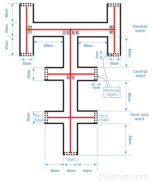
Schematic diagram of the courtyard structure
Tasks can be simply divided into three parts:
(1) Patrol line movement. Completing the most basic mobile function is the foundation of all functions. This work adopts a grayscale sensor tracking and a stepper motor line inspection and movement scheme.
(2) Identify the number of ward numbers. Visual microcontrollers such as openmv, k210, and raspberry pie can be used for recognition. Due to the lack of preparation for k210 in advance and the large size and power consumption of raspberry pies, the most common openmv was adopted. To ensure sufficient performance, openmv4plus is used.
(3) Dual machine communication. This work adopts Bluetooth dual communication to achieve data sharing.
After completing the above three tasks, it is the idea and idea for the logic of the car code. The next step is to debug multiple codes and fix bugs.
System solution
1. Microcontroller selection
Adopts the arduino ATMEGA2560 microcontroller as the main control. Due to its open source nature and simple code, it is suitable for beginners to use. Powerful library functions can greatly reduce development time. And for this question, the computational speed is sufficient, so it is adopted.
2. Sports system
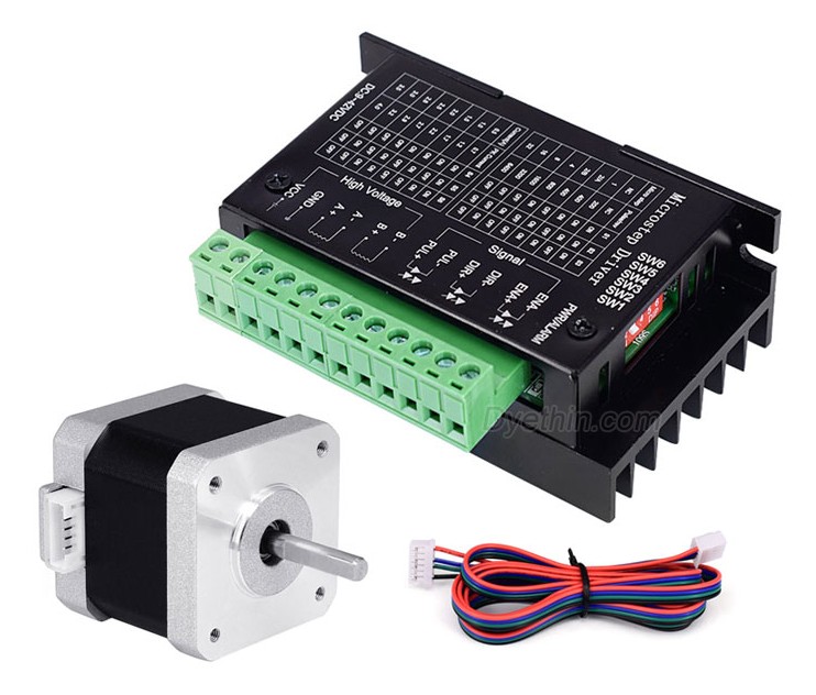
Using a 42 step motor. This motor has high rotational accuracy, large torque, rated current below 2A, and simple control. It will not cause deviation in the number of rotation steps due to different driving voltages. It can walk out of a very good straight line without the use of closed-loop control, and is not easy to deviate. It can accurately control the movement displacement in a short distance. The drive adopts TB6600 H-bridge bipolar constant phase current drive. The drive and motor are equipped with Taobao finished product kits, with a drive subdivision set to 800. Due to the large volume of the drive and the low current of the 42 stepper motor during operation, the metal casing (heat sink) of the drive module can be removed, thereby greatly reducing the volume and weight. There are also many types of stepper motor drives in the market, and it is recommended to buy dual circuit ones, which are more compact.
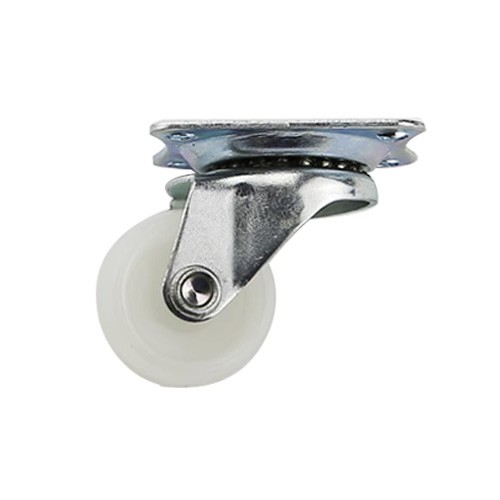
The front wheels are supported by bull eye wheels. The best choice for a cow's eye wheel is one with low friction. The cow eye wheel used in this work has a high friction force, which prevents the speed of the motor from being raised too high. Otherwise, the friction force will disrupt the vehicle's movement posture and cause it to tremble and tremble when walking. Therefore, it is recommended to use universal wheels, which can greatly reduce friction!!!
3. Tracking system
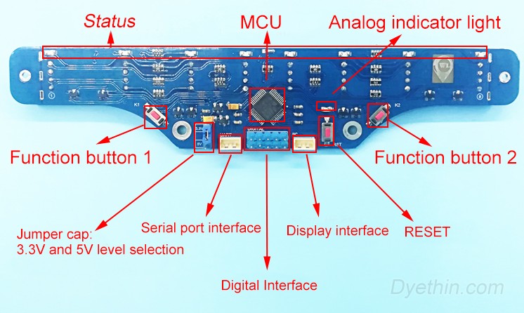
Eight grayscale sensors are used (only four are actually used). By adjusting the threshold well, it can accurately distinguish red and white. It is recommended to use the grayscale sensor shown in the figure below. By using a very simple digital logic to detect the tracking code, the tracking function can be completed.
4. Visual system
The handheld ward number adopts template matching recognition, because the handheld ward number can dynamically adjust the distance and angle, and template matching can also quickly recognize successfully.
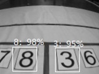
The number of ward numbers on the ground is recognized using the OpenMV4 H7 Plus neural network method. Compared to template matching, the recognition success rate is extremely high, reaching over 90%. Due to performance limitations, the runtime image only has 2-3 frames, and it is necessary to pause for a few seconds before the ward number to stabilize the image and recognize the digits.
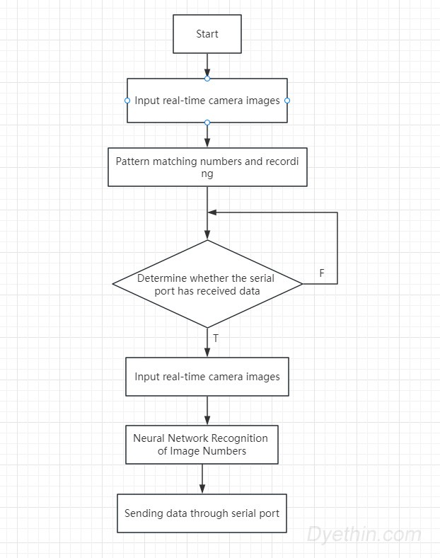
Once powered on, OpenMV executes a template matching algorithm to recognize the handheld ward number. After recognition, it sends the corresponding number to the microcontroller, and then OpenMV saves the "destination ward number" on its own. Afterwards, wait for the microcontroller to send '1'. Subsequently, the microcontroller controlled the car to stop at the intersection, and after sending '1', OpenMV used a deep learning algorithm to identify the ground ward number and compared it with the previously stored 'destination ward number'. If the left ward number and 'destination ward number' pasted on the ground are consistent, '1' will be sent, '2' will be sent if the right ward number is consistent, and '0' will be sent if they do not match. The microcontroller controls the car based on the received 0, 1, and 2: go straight to the next intersection and resend '1', turn left to the destination ward number, and turn right to the destination ward number.
5. Communication system
Using HM-10 Bluetooth module for dual machine communication. The master Bluetooth can only receive information from the slave Bluetooth and cannot transmit information to the slave Bluetooth. Therefore, connect vehicle 1 from Bluetooth and vehicle 2 from the main Bluetooth. Vehicle 2 only needs to receive instructions from Vehicle 1 to complete all tasks. Attention: It is necessary to set the master-slave mode and automatically connect to Bluetooth using AT commands in advance.
6. Other
The OLED screen is used to display whether the reading of the ward number was successful, and to display the running status of some small cars in real-time for easy debugging. Set red, green, and yellow indicator lights, buzzer prompts, and other functions.
Use the bilateral self reset button as the reset button. Due to the inconsistent working levels between the main microcontroller and OpenMV, the reset pin cannot be connected to the same button. Therefore, using this button can reset both microcontrollers with one click.
Drug detection uses a simple infrared obstacle avoidance module to detect high and low levels.
Schematic circuit analysis
1. Main control microcontroller expansion board
Due to the fact that the PCB in this work was prepared in advance and many functional interfaces were preset but not used, only the schematic diagrams of the previously used parts are explained.
(1) Single chip microcomputer and its pin external connection
The D2-D5 of Arduino serves as the IO port to connect to the motor drive module, driving two stepper motors (each controlled by DIR and PUL). Some pins of D23-D37 are connected to the 8 digital signal ports of the grayscale sensor.

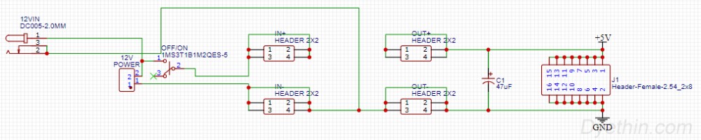
2) Power input and output
12V is input from the circular hole DC5.5 series interface, with one direct output supplying power to the stepper motor drive and stepper motor, and the other direct output supplying power to other modules such as the microcontroller through a 5V voltage regulator module. Introduce 8 sets of 5V power interfaces for easy expansion.
(3) Buzzer drive circuit

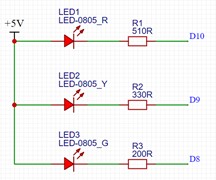
(4) Traffic light driving circuit
There is no such design in the schematic diagram. This is made by on-site soldering circuit, and the three lights are respectively connected to the D8, D9, and D10 interfaces of the microcontroller.
2. Stepper motor drive signal integration board
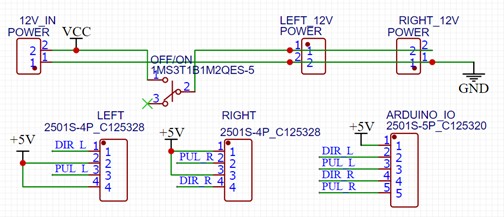
Two stepper motors require two drive boards and require a lot of signal and power cables, which can lead to messy and loose wiring. For better stability, this signal integration board was made and XH2.54 red and white patch cords were used, which are not easily loose and easy to plug and unplug.
(1) Schematic diagram
Divided into 12V power input and output, with wiring matching the IO distribution of the microcontroller expansion board.
(2) PCB and simulation diagram
The printing layer has added the corresponding IO port number and marked the status of the encoder corresponding to the stepper motor drive sub fraction. And the PCB hole position and size are fully compatible with the stepper motor drive module after removing the heat dissipation shell, which can be directly installed on the drive, saving space.
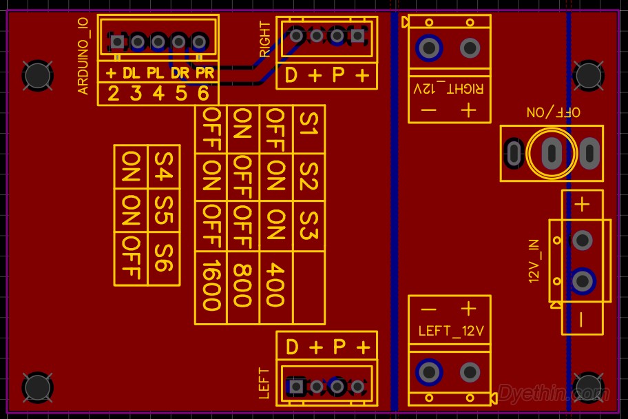
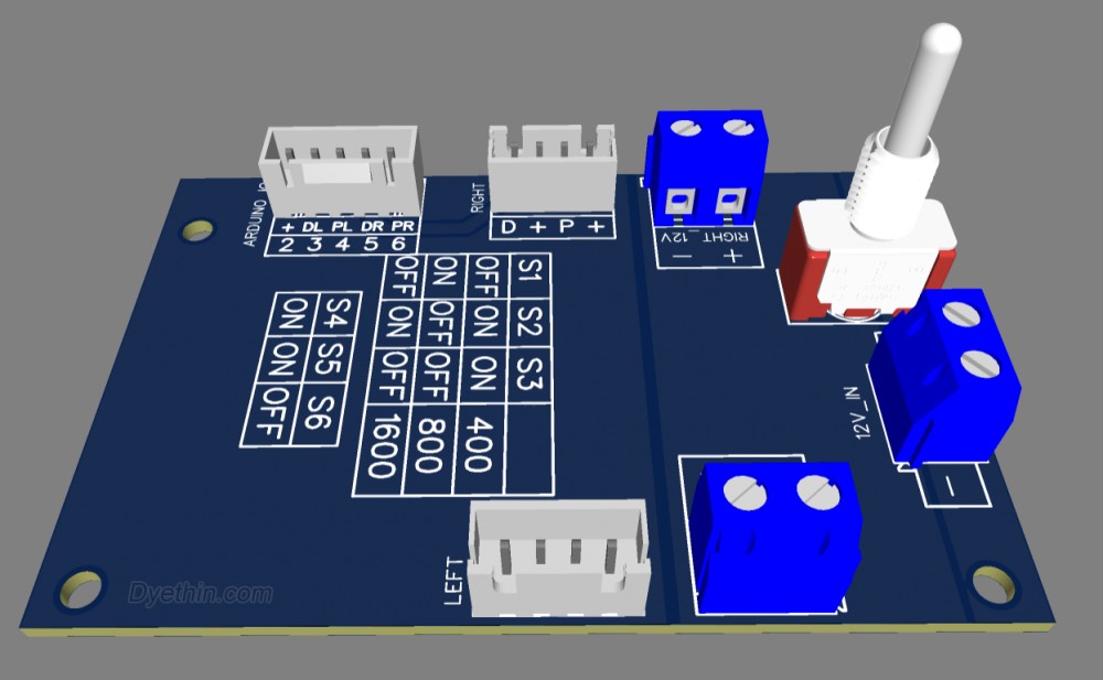
PCB design analysis
Due to the main difficulty in electronic control programming, the wiring difficulty for PCBs is relatively small, with a certain foundation and no special attention needed.
Physical display
Both car 1 and car 2 use the same scheme and model. Due to cost reasons, our team only has one openmv4plus on hand, while deep learning can only run with 4plus. Therefore, the car 2 is equipped with openmv4 and uses template matching for recognition.
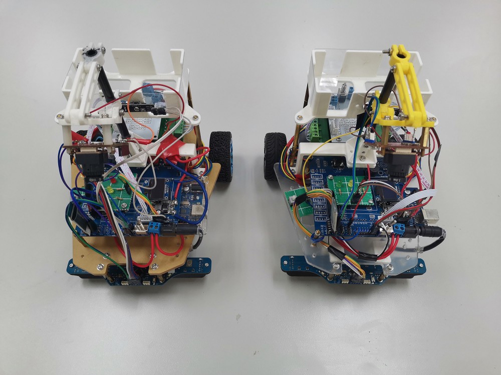
Work Assembly
1. Vehicle model
The figure shows the 3D mechanical structure of the small car. The front wheel is supported by two bull eye wheels, while the rear wheel is a power wheel driven by a stepper motor. 21cm in length, 19.5cm in width, and 24.5cm in height.
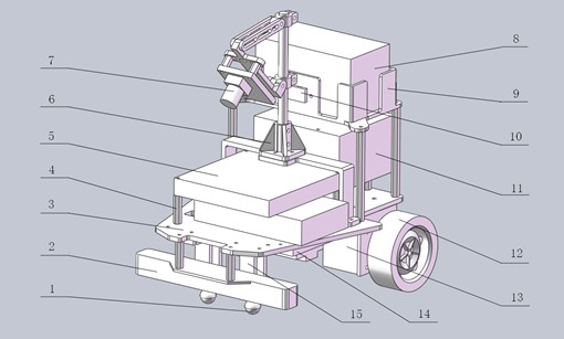
In the picture
1 is the ox eye wheel
2 is an eight channel grayscale sensor module
3 is the bottom plate of the car
4 is a hexagonal copper column
5 is the microcontroller and PCB expansion board
6 is the fixed base for the camera bracket
7 is an OpenMV camera
8 for drugs
9 is the medicine warehouse
10 is the infrared targeting module
11 is the stepper motor drive board
12 is a regular wheel
13 is a stepper motor
14 is a 12V lithium battery
15 is the support seat.
2. Car chassis diagram
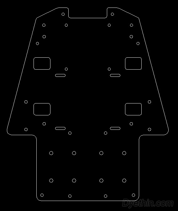
The picture is a CAD drawing of the car chassis, made of laser cut acrylic. The thickness is about 4mm.
Programming
1. Motion function
Taking forward as an example: controlling the number of steps of a stepper motor through the number of pulses. To make the motor run one revolution, it is necessary to give 800 pulses, with displacement corresponding to the circumference of the wheel. The speed (frequency) of the pulse determines the speed of motor rotation.
The reverse and counterclockwise directions are the same, except that the directions of motors A and B are different.

2. Tracing function
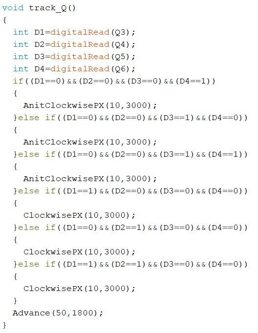
Q3-Q6 is the middle four grayscale sensors, which detect their level and control the left and right turns of the car based on the level. In the function: (Anit) Clockwise PX (103000) is the counterclockwise micro motion function, 10 is the number of steps, and 3000 is the speed (smaller, faster). Advance (501800) is the forward function, 50 is the number of steps, and 1800 bit speed.
3. Read ward number function
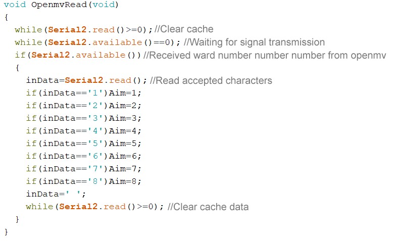
Among them, inData is a character type global variable that stores received information and serves as a cache. Aim is a global variable for the destination, and its numerical value represents the recognized destination ward number.
4. Read the ward number function at the fork intersection
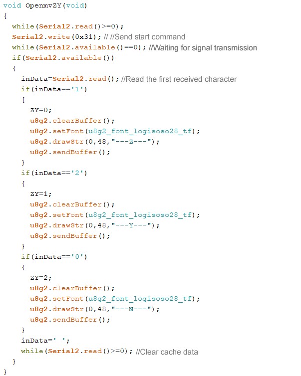
Customize the communication protocol with openmv, and start recognizing the ward number at the intersection when sending 0x31. Received the returned characters, corresponding to left turn, right turn, and forward, and the display screen will also display the corresponding Z, Y, and N. The u8g2 class function is a display function of OLED, and the usage method is self-learning and relatively simple.
5. Car 1 sends position information to Car 2
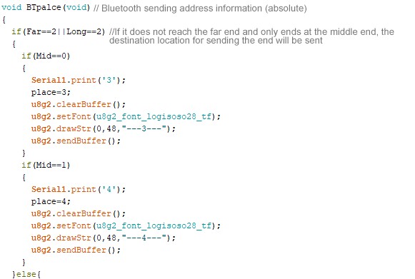
Define the absolute coordinates of the ward number, and send the absolute coordinates of the receiving point after Car 1 arrives (3 or 4, currently not achieving the task of 5-8). After receiving this absolute coordinate, Car 2 reaches the pause point. After the return of Car 1 is completed, it will send a runnable command to Car 2. At this time, Car 2 will directly go to the corresponding mid end ward based on the received absolute coordinates.
The code was not truncated completely because the absolute coordinates for sending 5-8 remote ward numbers were not achieved, and this part is of little use. The Mid variable in the function records the action of car 1 when it arrives at the mid end ward. Mid=0 corresponds to a left turn, Mid=1 corresponds to a right turn, and Mid=2 moves forward. Based on this, it can be determined whether the endpoint of Car 1 is in the mid end ward or the remote ward. The same variable is Long.
6. Visual code flowchart
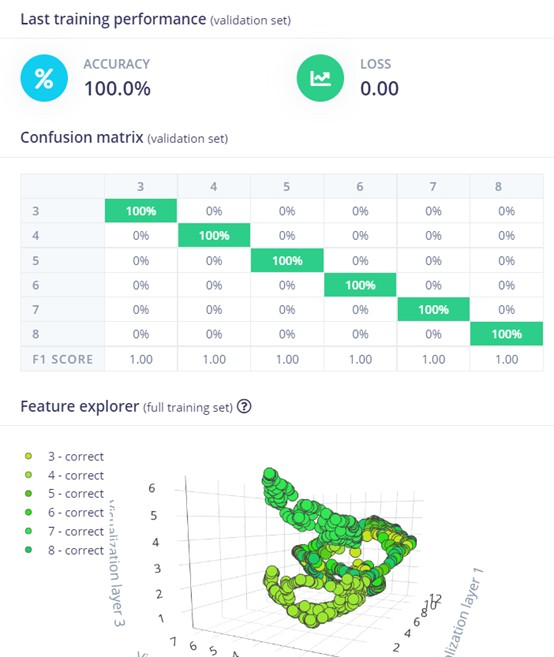
7. Neural Network Training Results
The results of training based on partial image data have reached 100% recognition rate. The actual detection result has a confidence level of over 90%, which is sufficient to meet the recognition requirements.
Resource file
Articles you may also like
NE555 datasheet and Pinout, NE555 circuits generates square waves
Hall Effect Sensors & Switches
RS485 chip selection and instructions
RS485 chip selection and instructionsRS485 chip selection and instructions