


- Home
- Blogs
- Simulation Technology
- Differential op amp and instrumentation amplifier applications
Differential op amp and instrumentation amplifier applications
How to handle the small-signal front-end has recently sparked a flurry of discussion. Customers of distributor Dyethin Electronics presented and analysed issues such as small-signal front-end, determination of measurement range, noise suppression, and signal-to-noise ratio enhancement.
Investigating the Construction of Operational Amplifiers
Certain engineers stress that the gain of the optimal operational amplifier is infinite. Prior to analysing the op amp, they focus on virtual breaks and shorts, disregarding concepts such as common-mode rejection ratio, offset voltage, and bias current.
Input model of the operational amplifier
In accordance with the operational amplifier model, the operational amplifier's fundamental model is characterised by the superposition of differential mode and common mode signals.

The notion of fictitious brief
Ideal operational amplifiers must consider virtual gaps and virtual shorts. The op amp's non-inverting and inverting inputs are equivalent.

In theory, the open-loop gain of an ideal operational amplifier is infinite, but in practise it is typically around 100dB (100000 times). According to this gain, only a 30uV voltage difference between the inverting and phase-input terminals is required to alter the output by 3V. Waves, noise, and other interference signals, at the same and opposite phase terminals, essentially remain unchanged. To create a closed loop, feedback is introduced, and the voltage difference between the same and opposite phase terminals is neglected.
3.Common mode input and differential mode input
In the application, the operational amplifier can accept either differential mode or common mode signals. The majority of common mode signals are caused by noise. The core vision is to eliminate the common mode and amplify the differential mode.

Spectrum of input voltage (Vin or Vcm)
The operational amplifier's input range is relatively complex. Theoretically, the analogue inputs of the non-inverting terminal and the inverting terminal can be satisfied by the power supply's positive and negative rails. The operational amplifier's upper and lower tubes are approximately symmetrical. Typically, the common mode of the operational amplifier is utilised. The input voltage Vcm is half of the supply voltage Vdd. Thus, the op amp operates predominantly in the linear region.

Method for small signal detection
When the operational amplifier is used to collect small current signals, it frequently encounters the dilemma of whether to use high-side current detection or low-side current detection to collect the signal.

A Review of Differential Amplifiers
Since the sensor signal is primarily output by applying a voltage difference, the signal's difference voltage is very small, causing layout and wiring-related issues such as EMI, common-mode interference, and temperature drift. As long as the sensor signal is provided in the middle of the non-inverting and inverting terminals of the operational amplifier, the relative interference will be significantly reduced. In order to prevent anomalous saturation of the op amp and to implement a differential amplifier, there is a pressure difference in the sensor's signal.

Due to cost considerations, the majority of designs in the industry utilise standard operational amplifiers and construct a differential amplifier based on the subtractor model.

Comparing the differential amplifier to a mirror illustrates its operating principle. It is termed a mirror image in physics. It is symmetrical and well-balanced. Only when the two sides are identical will the effect be optimal. Engineers must perform impedance matching in the analogue front end for this purpose. And because each point's reference source is unique and the impedance has errors, impedance matching is frequently extremely challenging. The diagram below depicts a conventional differential op amp. KCL is used to solve the non-inverting input and inverting input impedance by outputting the silent voltage Uoz, and the results are very distinct.

This section explains how to ascertain the value of each resistor in the figure above.
First, according to the mirror image principle, the bias current is also amplified by the same multiple, and the relationship between the four resistors can be determined; to determine R1, it is necessary to check several constraints of the operational amplifier, and the resistance value must satisfy the following conditions: greater than the instantaneous output voltage /Maximum output current, less than input offset voltage /input bias current, but also pay attention to the influence of therma.
Instrumentation Amplifiers: A Primer
The differential amplifier can manage the majority of the analogue front end, but complex matching circuits must be added due to the system's limited input impedance. When peripheral resistance accuracy and PCB line impedance converge, new issues will emerge.
In order to solve the problem of differential op amps' low input impedance, major manufacturers have performed extensive optimisation, and some of them use the dual op amp method to achieve instrument amplification, as depicted in the figure below.

The dual operational amplifier has two flaws: it does not support unity gain, and its common-mode rejection of various frequencies is subpar. Numerous manufacturers employ the three op amp technique. The instrumentation amplifiers introduced by numerous prominent manufacturers are also based on the three operational amplifier principle.

Microchip Op Amp Solutions
Instrumentation amplifier MCP6N16-100
In contrast to the three-op-amp instrumentation amplifier solution introduced by many manufacturers, Microchip has proposed an indirect current feedback instrumentation amplifier for industrial customer applications. Its inner structure is depicted in the diagram below:

The first stage of the instrumentation amplifier with indirect current feedback performs transconductance amplification to realise V-I conversion, while the second stage performs transimpedance amplification for I-V conversion.

There are a few distinctions between an indirect current feedback in-amp and a three-op amp in-amp, but the primary benefits are:
● High rail-to-rail CMRR over a broad Vcm range
● Extensive working space (Vin and Vout)
● Suitable for applications involving minimal voltage
● There is no "Hex" diagram
● input with high impedance Vref
● Better Gain Temperature Coefficient Matching
Application Case - Wheatstone Bridge

MCP6V61 Zero-Drift Amplifier
Moreover, Microchip's zero-drift amplifiers are primarily designed for low-cost applications. The primary attributes are:
High DC precision
- VOS fluctuation: 15 nV/°C
- AOL: 125 dB
- PSRR: 117 dB
- CMRR: 120 dB
- (EMIRR) at 1.8 GHz: 101 dB
- Low power consumption
- Quiescent current 80uA
Example Application - RTD Sensor

Articles you may also like
SMD Resistor Size Chart
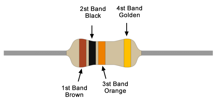
Understanding 10K Ohm Resistor: 10K Ohm Resistor Color Code
What is a 1K ohm resistor? 1K resistor code
Stepper motor drive based on ULN2003, refer to ULN2003 Datasheet and Pinout

-

-

-

-

-

-

-

-

richtek-usa-inc
Buck Switching Regulator IC Positive Adjustable 0.765V 1 Output 3A SOT-23-6 Thin, TSOT-23-6
-

texas-instruments
Buck, Split Rail Switching Regulator IC Positive Adjustable 0.8V 1 Output 3.5A 8-PowerSOIC (0.154