


- Home
- Blogs
- Simulation Technology
- Stepper motor drive based on ULN2003, refer to ULN2003 Datasheet and Pinout
Stepper motor drive based on ULN2003, refer to ULN2003 Datasheet and Pinout

1. What is ULN2003 IC?
The motor driven ULN2003 IC is an integrated circuit that can control the speed, direction, and torque of the motor. It can receive analog or digital signals as control signals, usually including some type of feedback from the motor, such as position, speed, current, and temperature, to ensure the normal operation of the motor.
The ULN2003 is high voltage, high current Darlington arrays each containing seven open collector Darlington pairs with common emitters Each channel is rated at 500 mA and can stand peak currents of 600 mA. Suppression diodes are included for inductive load driving and the inputs are pinned opposed to the outputs to simplify board layout.
These versatile devices are useful for driving a wide range of loads including solenoids, relay DC motors, LED display filling lamps, thermal printheads and high power buffers
The 2003A is supplied in a 16 pin DIP package with a copper lead frame to reduce thermal resistance They are available also in small outline package (SO-16) as 2003D1
ULN2003 is also available in TSSOP16 package for reduced application space
2. ULN2003 IC Features
• Seven Darlingtons per package
• Output current 500 mA per driver (600 mA peak)
• Output voltage 50 V
• Integrated suppression diodes for inductive loads
• Outputs can be paralleled for higher current
• TTL/CMOS/PMOS/DTL compatible inputs
• Input pins placed opposite to output pins to simplify layout
3. Application scope of ULN2003 IC
We can know from ULN2003 Datasheet its wide range of applications.
ULN2003 is a high voltage, high current composite transistor array consisting of 7 silicon NPN composite transistors, with each pair of Darlington transistors connected in series with a 2.7K base resistor. At a working voltage of 5V, it can be directly connected to TTL and CMOS circuits, and can directly process data that originally required standard logic buffers. This IC is commonly used in control circuits such as microcontrollers, intelligent instruments, PLCs, and digital output cards, and can directly drive loads such as relays and small motors.
4. ULN2003 Schematic diagram

5. IC ULN2003 Pinout

ULN2003 Pinout
The pin arrangement of ULN2003 may vary depending on the packaging form. Generally speaking, it includes input pins, output pins, as well as power and ground pins. The specific pin arrangement diagram can be found in the relevant data manual or information provided by the manufacturer.
The data comes from ULN2003 Datasheet. For more information, please refer to ULN2003 Datasheet
6. Usage of ULN2003 Circuit
Firstly, connect the power pin of ULN2003 circuit to the appropriate positive pole of the power supply, and connect the ground pin to the ground terminal.
As needed, connect the input signal (analog signal or digital signal) to the input pin of ULN2003 circuit.
Connect the load that needs to be driven (such as a motor or relay) to ULN2003 pinout.
As needed, external components such as resistors, capacitors, etc. can be used for stability and protective adjustments.
Ensure that the selected components (such as resistors, capacitors, etc.) have voltage and temperature resistance parameters that meet the application requirements.
7. Tips for using ULN2003 Circuit
To ensure the stability of the circuit, it is recommended to add appropriate capacitors at the input and output terminals for filtering.
When using ULN2003 circuit to drive inductive loads (such as motors), it is recommended to parallel freewheeling diodes at both ends of the load to protect the transistor from the impact of reverse voltage.
To avoid electromagnetic interference (EMI) issues, the ULN2003 circuit can be kept at a certain distance from other sensitive circuits or filtered using magnetic beads.
When using multiple ULN2003 circuits in parallel to improve output current capability, it is necessary to ensure good thermal coupling and current balance between each IC.
When designing a PCB, ensure that there is sufficient space around the ULN2003 circuit for heat dissipation. At the same time, avoid placing thermal sensitive components near them.
8. Advantages and disadvantages of ULN2003 IC
Advantages:
High voltage resistance and high current: ULN2003 IC can withstand high voltage and current, suitable for driving various loads.
Wide working voltage range: ULN2003 IC can operate normally within a wide working voltage range, making it convenient to adapt to different power supply voltage requirements.
Easy to connect with TTL and CMOS circuits: ULN2003 IC can be directly connected to TTL and CMOS circuits, simplifying interface design.
High speed response: ULN2003 IC has a fast switching speed, suitable for application scenarios that require fast response.
There are various packaging forms: ULN2003 IC provides multiple packaging forms, making it easy to integrate and apply in various electronic devices.
Relatively low price: The price of ULN2003 IC is relatively low, which reduces product costs.
Disadvantages:
High power consumption: ULN2003 IC generates a certain amount of power consumption during operation, and attention should be paid to heat dissipation design. For high-power applications, more efficient driver ICs can be considered as alternatives.
Limited current capability: Although ULN2003 IC has high output current capability, it may still be insufficient in some high current applications. At this point, multiple ULN2003 can be used in parallel to improve the output current capacity, but it will increase the complexity and cost of the design. Therefore, when selecting ULN2003 IC, it is necessary to fully consider whether its output current capacity meets the application requirements.
9. Stepper motor drive based on ULN2003
Basic principles of stepper motors
In our testing, we used a 4-phase 5-wire stepper motor. The so-called 4-phase 5-wire stepper motor refers to a motor with 4 sets of coils and 5 connecting wires. In fact, there may be more than 5 wires, but no matter how many wires are pulled out from the common end, the actual state is no different from 1 wire.
We usually label these four groups of coils as A phase, B phase, C phase, and D phase. Of course, other names can also be used as long as they are easy to label separately. A 4-phase 5-wire stepper motor is generally powered by a unipolar DC power supply. As long as the phase windings of the stepper motor are energized in the appropriate timing, the stepper motor can rotate in steps. Generally, motors will provide control tables, as shown below:

Based on the ULN2003A structure and the driving requirements of a 4-phase 5-wire stepper motor, we can design a driving circuit for the ULN2003A Darlington transistor to drive a 4-phase 5-wire stepper motor.

Stepper motor drive mode
Although the driving of stepper motors can be achieved according to the motor's driving table, there are various actual driving methods, such as single wave driving, full step driving, half step driving, and micro step driving. Here we can take a look at the first three relatively simple driving methods.
The single wave drive mode is also known as the single four beat working mode. This method drives each coil in a fixed order to achieve the purpose of turning the motor. Its waveform is as follows:

The full step driving mode is also known as the dual four beat working mode. This method drives two sets of coils in a fixed order to achieve the purpose of rotating the motor. Its waveform is as follows:

The half step driving mode is also known as the eight beat working mode. This mode is actually a combination of the first two modes, which sequentially excites one or two sets of coils in a fixed order to achieve the purpose of driving the motor. Its waveform is as follows:

The above waveforms are the waveforms of phase A and phase C captured using an oscilloscope in single wave driving mode, full step driving mode, and half step driving mode, which can basically display the waveform characteristics of these driving modes.
Driver Design and Implementation
We have understood the basic working situation of ULN2003A driving a 4-phase 5-wire stepper motor. Next, we need to use this to design and implement the driver program for ULN2003A driving a 4-phase 5-wire stepper motor.
Object Definition
We still implement related operations based on objects. So first, we need to define the object. For applicability reasons, we need to define the type of the object and instantiate the specific object. Next, we will abstract the object type and instantiate the operation of the object.
Abstraction of objects
For an object, it mainly includes two aspects: properties and methods. Therefore, let's first consider which properties and methods drive a stepper motor object, and abstract a more general type of stepper motor object.
Firstly, let's consider the properties of the object. The operation of the motor includes start stop commands, direction commands, operating status, actual operating direction, beat number, cycle, etc. These information control the operation of the motor and characterize its specific working status, so we consider it as an attribute of the object. The driving mode and operating mode are used to configure the specific working mode of the motor, so we also use them as properties of the object to complete the configuration of the object.
Next, let's consider the method of the object. The specific operation of phase is related to the specific hardware platform, and the corresponding phase pins are defined based on the corresponding pins. This depends on the specific hardware and software operating platform, so we define it as the method of the object. In order to control the timing of operations, we need to delay processing, and the delay operation function also depends on the specific software and hardware platform. Therefore, we define it as a method of objects and implement it through callback functions.
Based on the analysis of object properties and methods mentioned above, we can define the types of stepper motor objects as follows:
/*Define the type of stepper motor object*/
Typedef struct StepperObject{
Uint8_ T startStop // Start stop command
Uint8_ T runStatus // running state
Uint8_ T directSet // Direction setting
Uint8_ T directRun // Current direction
Uint8_ T beat // Current beat
Uint8_ T period // Speed control cycle
DriveModeType driveMode // Drive mode
StepperModeType runMode // Operation mode
Void (* PhaseAction) (uint8_t cmd);
Void (* Delayms) (uint32_t period);
}StepperObject Type;
Object initialization
We have defined object types to enable object based operations, but the defined object variables need to be initialized in order for different objects to run according to our configuration. So before starting to use the object, we first initialize it, which requires us to design an object initialization function.
This initialization function will construct a specific operation object. For stepper motors, we need to initialize their related parameters, such as working mode, operating mode, and phase operation function. The specific initialization function is as follows:
/*Stepper motor object initialization*/
Void Stepperinitialization (StepperObject Type * Stepper, //Stepper motor object
DriveModeType driveMode, //Drive Mode
StepperModeType runMode, //RunMode
Uint8_ T period, //Speed control cycle
StepperPhaseActionType action, //Phase operation callback function
StepperDelaymsType delays //Delay operation callback function
)
{
If (stepper==NULL) | | (action==NULL) | (delays==NULL))
{
Return;
}
Stepper ->PhaseAction=action;
Stepper ->Delayms=Delayms;
Stepper ->driveMode=driveMode;
Stepper ->runMode=runMode;
Stepper ->period=period>0? Period: 1;
}
Object operation
Next, we will consider the operational issues to be carried out on the stepper motor object. We have defined the specific hardware platform oriented operation of phase as an object oriented method. We need to control the rhythm operation of objects in different modes. The specific implementation is as follows:
//Stepper motor rhythm operation
static void StepperAction(StepperObjectType *stepper)
{
uint8_t Command[BEAT_NUM]={0x01,0x03,0x02,0x06,0x04,0x0C,0x08,0x09};
RunBeatType beat=BEAT_NUM;
if(stepper->beat>=BEAT_NUM)
{
stepper->beat=0;
if(stepper->driveMode==Full_Step)
{
stepper->beat=1;
}
}
beat=stepper->directRun>0?((RunBeatType)(7-stepper->beat)):((RunBeatType)stepper->beat);
if(beat>=BEAT_NUM)
{
return;
}
stepper->PhaseAction(Command[beat]);
stepper->beat++;
if((stepper->driveMode==Full_Step)||(stepper->driveMode==Single_Wave))
{
stepper->beat++;
}
stepper->Delayms(stepper->period);
}
Driver applications
We have designed and implemented a stepper motor driver program based on ULN2003A. Next, we will implement an example to verify whether this driver program setting meets the requirements.
Declare and initialize objects
Before starting all operations, we first need an object. In the previous design, we have already defined a StepperObject Type object type, so we use it to define an object variable.
StepperObject Type chamber;
After defining the chamber object variable, it cannot be used yet because we need to initialize it. We have already designed an object initialization function earlier, and we need to use this function to initialize the chamber object variable. The initialization function requires the following parameters:
StepperObject Type * stepper, //Stepper motor object
DriveModeType driveMode, //Drive Mode
StepperModeType runMode, //RunMode
Uint8_ T period, //Speed control cycle
StepperPhaseActionType action, //Phase operation callback function
StepperDelaymsType delays //Delay operation callback function
The first parameter is the stepper motor object that we need to initialize. The driving mode and operating mode are enumeration, and can be inputted according to actual usage requirements. The speed period is set as the initial speed, as long as it is not an integer of 0. The main consideration is the following two function pointers. The prototype definition is as follows:
Typedef void (* StepperPhaseActionType) (uint8_t cmd);
Typedef void (* StepperDelaymsType) (uint32_t period);
Based on the prototype definition of function pointers and the specific hardware configurations used in our project, we can implement phase operation functions as follows:
/*Stepper motor phase operation*/
static void PhaseOperation(uint8_t cmd)
{
GPIO_PinState AP,BP,CP,DP;
AP=(GPIO_PinState)(cmd&0x01);
BP=(GPIO_PinState)((cmd>>1)&0x01);
CP=(GPIO_PinState)((cmd>>2)&0x01);
DP=(GPIO_PinState)((cmd>>3)&0x01);
HAL_GPIO_WritePin(GPIOE, GPIO_PIN_9, BP);
HAL_GPIO_WritePin(GPIOE, GPIO_PIN_11, DP);
HAL_GPIO_WritePin(GPIOE, GPIO_PIN_13, AP);
HAL_GPIO_WritePin(GPIOE, GPIO_PIN_14, CP);
}
And for the delay function, we directly use HAL_ Delay, so we can achieve the initialization operation of the stepper motor object as follows:
/*Stepper motor object initialization*/
StepperInitialization(&chamber, //Stepper motor object
Half_Step, //drive mode
Mode_Speed, //Operating mode
10, //Speed control cycle
PhaseOperation, //Phase operation callback function
HAL_Delay //Delay operation callback function
);
Object based operations
After initialization, we can use this object to achieve the desired operation. We design an application function that calls related drivers to implement operations.
We can achieve the following position control modes:
StepperPositionControl (&chamber, 5000, Direct-CW);
We can achieve speed control modes as follows:
StepperSpeedControl (&chamber);
Of course, the specific operating mode needs to be configured in the initialization function.
Conclusion
In this article, we designed and implemented a stepper motor driver program based on ULN2003A. The test example we designed runs normally. In fact, this driver has been actually used in our project and has been running steadily so far.
At the beginning, we mentioned that it is aimed at low-voltage low-power stepper motors, but in reality, if we control the MOS transistor through ULN2003A, we can achieve high-voltage high-power stepper motors. However, we directly use ULN2003A Darlington transistors, so it is limited to low-voltage low-power stepper motors.
When using a driver, it is important to note that it does not support high operating speeds. When the speed is high, there may be situations where the torque is too small and the rotor is blocked. The motor used in our experiment is generally controlled below 250Hz and can operate stably.
When designing the stepper motor drive process based on ULN2003 Datasheet PDF, people will also pay attention to the following information:
| uln2003 pinout | uln2003apg | uln2003l | uln2004 application circuit | uln2003 driver |
| uln2003 circuit | 28byj 48 datasheet | uln2003 stepper motor driver board | uln2003 applications | uln2003an datasheet |
| uln2003 ic circuit diagram | uln2003 arduino | uln2003 relay driver circuit | sbto811 | uln2003 ic circuit diagram |
| uln2003 datasheet pdf | uln2003a arduino | uln2004 pinout | uln2003 working microcontroller | uln2003 relay driver |
| uln2003 ic datasheet | uln2004a | libreria stepper arduino | uln2003 amazon | uln2003 smd |
| uln2003 price | uln2003 pinout | uln2003 price | uln2003 vs l293d | uln2003apg datasheet |
| uln2003 input voltage | uln2003 stepper motor | uln2003 raspberry pi | uln2004 ic price | uln2003 vs uln2803 |
| l293d | uln2003 circuit | uln2003apg arduino | inventables caseros | uln2003 driver board datasheet |
| 74hc595 | uln2803 arduino | uln2003 input voltage | uln2003 datasheet | uln2003 input voltage |
| uln2803 | uln2003apg datasheet | uln2003 circuit diagram | uln2003a datasheet | uln2003 pin diagram |
| uln2004 | uln2003 smd | 28byj 48 max rpm | uln2003 ic |
Articles you may also like
SMD Resistor Size Chart
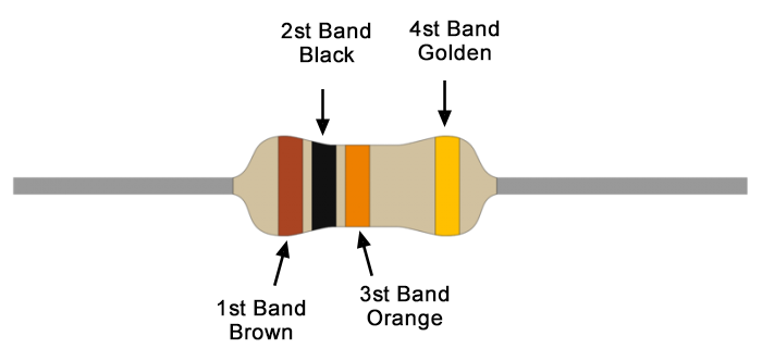
Understanding 10K Ohm Resistor: 10K Ohm Resistor Color Code
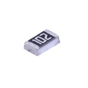
What is a 1K ohm resistor? 1K resistor code
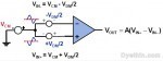
Differential op amp and instrumentation amplifier applications


