


- Accueil
- Blogs
- Semiconductor
- Accurately measure resistor value using ADC
Accurately measure resistor value using ADC
Many microcontrollers now have ADC functions, 10-bit or 12-bit. It is very convenient to use ADC to measure voltage.
Why Simple Voltage Divider Resistance Measurement Has Limited Accuracy
To measure the resistance of a resistor, you can use Ohm's law to divide the voltage and then measure the divided voltage to calculate the resistance of the resistor. value, the simplest resistance measurement circuit is as follows:

At this time, the voltage calculation formula of the measuring point is: Vo=R2 / (R1 + R2) * Uref.
This is the simplest method of measurement calculation. However, simplicity can also lead to many small problems. For example, if the value of R1 is 2K, Uref is 5V, and the resistance range of R2 is about 5 to 10 ohms, then the voltage divided by R2 Vo=0.01247 to 0.02488, the voltage changes The range of The variation range is 10-5=5 ohms, that is, the variation range of 5 ohms is calculated using the changes of 15 AD values, then the accuracy of AD measurement is: 5 ohms / 15 = 0.33 ohms, that is, the AD value plus 1 , the calculated resistance value must add 0.33 ohms, which is really unacceptable accuracy.
For another example, the values of R1 and Uref remain unchanged, and the resistance range of R2 is between 1K and 2K. The same calculation method obtains the partial voltage value of R2 Vo=1.1 to 1.65 volts, and the AD value ranges from 1365 to 2048, AD The measurement accuracy is: 1K/(2048-1365)=1.46. The strange thing is why the AD value range is so wide, but the accuracy is even worse? Because the value range of the resistor is very wide, the accuracy is reduced.
How a Bridge Circuit Improves ADC-Based Resistance Measurement
what to do? I want to measure the resistance R2 of a relatively precise resistor, what should I do? The following method is the method for measuring resistance by a bridge on the Internet. I have modified it for the convenience of measurement. The resistor network circuit is as shown below:

The resistance value of R2 is approximately 100 to 200 ohms. We take a reference resistor R3 as 100 ohms, and R1 and R3 have the same resistance value of 2K. This results in two partial voltage values, U1 and U2, where U2 is the fixed voltage U2=100/(100+2000) * Uref. The value of U1 varies according to the change in R2: U1=R2/(R2+2000) * ref.
Using an Operational Amplifier to Expand the ADC Measurement Range
After obtaining U1 and U2, the pressure difference can be calculated:
△ U=U1-U2, input these two voltages into the operational amplifier for reasonable amplification, so that the output voltage range obtained is as wide as possible within the ADC reference voltage range, so that the voltage value can be measured more accurately using ADC. The circuit for amplification using an operational amplifier is shown in the following figure:

In the case of R5=R6 and R7=R8, the amplification factor of the op amp is m=R7/R5. The amplification factor in the circuit is m=20. After being amplified by the op amp, Uo is obtained and sent to the ADC of the microcontroller system for AD sampling. Then we can calculate the relationship between the AD value measured by the ADC and the resistor R2.
How to Derive the Relationship Between ADC Value and Resistance
Now assume that the reference voltage of the ADC system is Uadc, the number of ADC sampling bits is 12 bits, and the measured value of the ADC is A, then the calculation formula of Uo is as follows:
Uo = A / 4096 * Uadc
And Uo is also the output voltage of the op amp. Calculation based on the bridge network and op amp can be obtained:
Uo = (U1-U2) * m = ( (R2/(R1+R2) - R4/(R3+R4) ) * Uref * m
That is to say:
( (R2/(R1+R2) - R4/(R3+R4) ) * Uref * m = A / 4096 * Uadc ---------------------------- ------①
In the above formula, R1, R3, R4, m, Uref, and Uadc are all known, then the resistance value of resistor R2 can be easily calculated based on the value A’ measured by the ADC.
How to Simplify Calibration by Setting Uref Equal to Uadc
The above is a theoretical calculation method, which is indeed the case, but the reality is often cruel. Since the resistors have errors and the op amp is not absolutely precise, then the known R1, R3, R4, m, Uref, Uadc Several parameters are slightly different from the real values. For example, the nominal resistance of resistor R1 is 2K, and the error is 1%. The resistance measured by a multimeter is 1980 ohms. Obviously, there is an error, so it can be directly entered into the formula. Calculation is not possible. then what should we do?
There is always a solution. In the previous formula ①, the resistance value of resistor R2 is calculated based on the measured value of ADC and several known parameters. Then we will do the opposite and use several sets of known fixed resistance R2 resistors to connect to the resistor network and measure AD. Value A is used to calculate the parameters R1, R3, R4, m, Uref, and Uadc. However, these parameters are a bit too many. Six unknown parameters require 6 sets of formulas to solve. It is very laborious, so we will simplify it. Calculation.
We set R4 to 0 ohm, that is, U2 is connected to GND, U2=0, so that equation ① can be simplified to:
R2/(R1+R2) * Uref * m = A / 4096 * Uadc ----------------------------②
It couldn't be easier! Okay, now we need to find the resistance value and amplification factor m of R1 in the formula. With two unknowns, we need two sets of known points (R2, A) to find the parameters R1 and m. In this way, take the test resistance of the first point as R21 and the AD value as A1, the test resistance of the second point as R22 and the AD value as A2, and bring them into equation ② to get:
R21/(R1+R21) * Uref * m = A1 / 4096 * Uadc
R22/(R1+R22) * Uref * m = A2 / 4096 * Uadc
Divide the above formula by the following formula to get:
(R21/(R1+R21)) / (R22/(R1+R22)) = A1 / A2
After sorting, we get:
R1=(R21 * R22) * (A2 - A1) / (R22A1 - R21 * A2)
This determines the resistance of R1.
Then we find the value of m. According to formula ②, we can get the calculation formula of m as:
m = (A / 4096 * Uadc) / (R2/(R1+R2) * Uref)
We connect the power supply of the resistor network and the reference power supply of the ADC system together, that is to say Uref=Uadc. We need to ensure the stability of the power supply. We can use high-precision voltage stabilizing chips such as TL431 or REF3030 to produce stable voltage sources for the resistor network and ADC system power supply. Since Uref=Uadc, the above formula is simplified:
m = (A / 4096) / (R2/(R1+R2))
Organized to get:
m = A(R1+R2) / (4096 * R2) ----------------------------③
In equation ③, R1 has been calculated before, so m can also be calculated.
Final Resistance Calculation Formula for Practical ADC Measurement
At this point we have found the values of R1 and m, and later we can find the value of the resistor R2 to be measured based on these two parameters and the measured AD value. Since Uref=Uadc, equation ② becomes:
R2/(R1+R2) * m = A / 4096
Organized to get:
R2 = A * R1 / (4096*m - A) ----------------------------④
Equation ④ is so simple that we only need A, R1, and m to calculate the resistance of R2, and the R1 and m used are the values we calculated ourselves, instead of directly using the theoretically calculated values, which improves the accuracy. A lot. At the same time, we can find that since Uref=Uadc, both ends of the above formula ② are reduced, and all calculations have nothing to do with Uref and Uadc. That is to say, no matter how Uref and Uadc change, as long as Uref and Uadc are always equal, The calculation of all parameters and resistance values does not involve Uref and Uadc. But we'd better ensure the stability of Uadc, otherwise the measured AD value will be inaccurate.
Articles you may also like

Characteristics of CPU, GPU, and FPGA
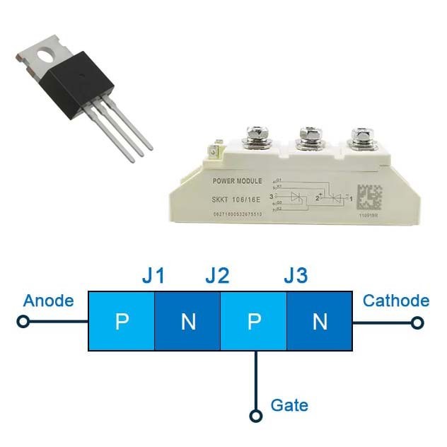
Silicon controlled rectifier (SCR) and switch control circuit explained
The difference between RAM ROM FLASH

What is a GPU? What is the relationship between GPU and graphics card?


