


- ホーム
- Blogs
- Intelligent control
- Measurement of Air Ionic Conductivity with Double Darlington Tubes
Measurement of Air Ionic Conductivity with Double Darlington Tubes
Ⅰ.Preface
The introductionMany years ago, TOM Petruzzellis penned the book Electronic Sensor Experiments for Geniuses, which contains a number of fascinating electronic sensor experiments.On the cover, the chamber sensor used to measure air ions should be the author's most impressive and magical invention.It is true that the materials required for this experiment are inexpensive, but the outcome is truly astounding. Through a simple metal ion chamber, that is, a metal wire fixed in the centre of a metal tank, after current amplification via two complementary Darlington low-power transistors, a 100 microampere ammeter is driven; a symmetrical one is located on the right. The primary function of the circuit is to compensate for temperature and humidity drift.Following is a brief overview of the handcrafted ion chamber manufacturing process.A circuit for a simple amplifier constructed on a breadboard.Examine the exact measurement results.Passing this test also prepares you for the subsequent circuit design of a high-impedance amplifier.Examine the function of this simple and enchanted ion chamber amplifier circuit.

II.Production method
1. Fabrication of the ion chamber
This ion chamber constructed from a metal beverage can is a sensor for measuring ions in the air. It consists of two parts. One is this beverage can made of aluminium.The second connector is a coax BNC connector.After using an electric drill to create a hole in the bottom of the metal pipe, attach the BNC to the bottom of the metal pipe. Before securing the BNC, weld a galvanised metal wire into its lead to serve as the ion chamber's central electrode.


▲ Figure 1.2.1 Two components for making the ion chamber
Fix the BNC connector to the bottom of the metal pipe, and weld a metal wire inside. This is the final installation effect.

2. Amplifying circuit
Introduce the circuit for amplification. Very little current is generated in the ion chamber, only a few dozen fA. It should be enlarged. To keep things simple, only half of the circuit is constructed on a breadboard. Utilise a cascade of two Darlington transistors to complete the current amplification. The two Darlington transistor models are BC517 and MPSA64.

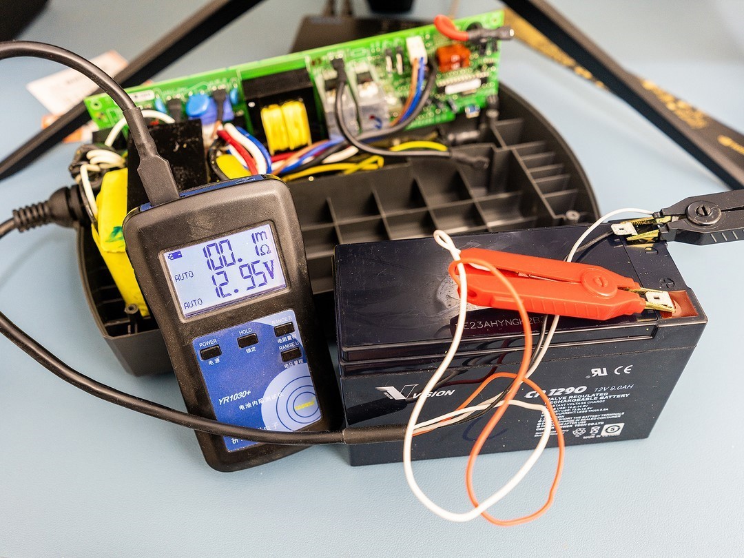
BC517 is the NPN Darlington transistor in the circuit, while MPSA64 is the PNP type transistor. Each triode is readily accessible. BC517's hFE parameter, or current amplification factor, is approximately 44000, and its pin distribution is C, B, and E, from left to right. MPSA64 was tested with the same equipment. It can be observed that its current amplification factor is approximately 41100, and its pin distribution is identical to that of BC517, namely C, B, and E from left to right.

Construct a current amplification circuit on a breadboard and connect a 10 microfarad capacitor in parallel to the collector of the PNP Darlington transistor to eliminate the 50Hz interference signal from the output voltage signal. This circuit is the left side of the original circuit, using a digital multimeter to directly measure the output voltage on R2.When observing the output voltage signal with an oscilloscope, increasing this capacitor can result in a more stable output waveform.

Figure 1.2.2 Circuit for current amplification
Connect the ion chamber to the measurement circuit using a shielded BNC cable. The circuit's operating voltage has been set to 9V. The voltage is determined by testing. If the operating voltage is too high, the amplification circuit described above is susceptible to saturation. If it is too low, the circuit's amplification factor will be diminished. Connect the voltage output to the digital multimeter and the signal to the oscilloscope. It can be seen that the output voltage of the circuit is approximately 0.6V at this time.

Ⅲ.Circuit test
Utilise this ionic smoke sensor to raise the ion concentration in the air.Americium 241 has weak radioactivity in its core, and the alpha rays it emits can be used to collect a large number of air samples.A large number of ions will appear in the air above the radioactive metal sheet as it disassembles.Utilise the front ion chamber to measure the surface ion current.

When the ion chamber is placed above the radiation source, the output voltage of the circuit is immediately saturated. Then, gradually recover thereafter.Place the radioactive source in front of the ion chamber for a period of time, and you will observe that the strong rays generate a large number of ions in the ion chamber's air. Consider it again from this perspective.


▲ Figure 1.3.1 Using ion source to ionize air
Using a butane torch to spray the ion chamber, it can be seen that the output voltage of the circuit is saturated instantly. This shows that a large number of ions are produced around the flame. This is a small lighter, which will also greatly increase the ions in the air. Smoke can reduce ions in the air.

Figure 1.3.2 Smoke can decrease the number of ions in the air
Summarize
This article discusses the experiment of using two Darlington transistors to amplify the ion current in the air. The two transistors are NPN type and PNP type Darlington transistors. Using metal beverage cans to make a simple ion chamber, testing the air ionization phenomenon produced by the americium-241 radioactive source, Using this device, we observed the phenomenon of ion conduction in the air.

Articles you may also like
What is a waveform? What types of waveforms are there? And the characteristics of the waveform
Build an intelligent UPS power supply

PIC microcontroller technology and application foresight
CC2530 integrated circuit IC to design an intelligent agricultural control system

-

-

-

-

-

-

-

-

-

omron-electronics-inc-emc-div
General Purpose Relays DPST-NO (2 Form A) 10 A 12VDC