


- Startseite
- Blogs
- Industry
- Inductor working principle and application analysis
Inductor working principle and application analysis

Inductors are fundamental components in electronic circuits, playing a crucial role in various applications. This article delves into the intricacies of inductors, exploring their definition, working principles, types, applications, and key parameters.
1. Introduction
An inductor is a passive electronic component that stores energy in its magnetic field when electrical current flows through it. It typically consists of a coil of wire and is characterized by its inductance, measured in henries (H). Inductors are essential in filtering, energy storage, and signal processing applications.
Inductor Symbol

2. Fundamental Principles of Inductance
Inductance is the property of an electrical conductor that opposes changes in current. When current flows through a coil, it generates a magnetic field, and any variation in this current induces a voltage opposing the change, as described by Faraday's Law of Electromagnetic Induction. The relationship is mathematically represented as:

Where V(t) is the induced voltage, L is the inductance, and  is the rate of change of current.
3. Construction and Core Materials
Inductors are constructed by winding a conductor, usually copper wire, into a coil. The core material around which the coil is wound significantly influences the inductor's performance. Common core materials include:
Air Cores: Used in high-frequency applications due to the absence of core losses.
Ferrite Cores: Made from ceramic compounds, offering high magnetic permeability and low electrical conductivity, ideal for high-frequency applications.
Powdered Iron Cores: Provide moderate permeability and are suitable for power applications due to their distributed air gaps, which help in managing core saturation.
4. Types of Inductors

Inductors come in various types, each suited for specific applications:
Fixed Inductors: Have a set inductance value and are commonly used in filters and oscillators.
Variable Inductors: Allow adjustment of inductance, useful in tuning circuits.
Chokes: Designed to block high-frequency AC signals while allowing DC to pass, used in power supply applications.
Toroidal Inductors: Feature a doughnut-shaped core, providing efficient magnetic field containment and higher inductance per turn, suitable for compact designs.
Multilayer Inductors: Consist of multiple layers of conductive coils, offering higher inductance in a smaller package, commonly used in surface-mount technology.
5. Key Specifications and Parameters
When selecting an inductor, several key parameters must be considered:
Inductance (L): The primary characteristic, measured in henries (H), indicating the inductor's ability to store energy.
Quality Factor (Q Factor): Represents the efficiency of the inductor, defined as the ratio of inductive reactance to resistance at a specific frequency. A higher Q indicates lower energy losses.
Self-Resonant Frequency (SRF): The frequency at which the inductor's capacitive and inductive reactances cancel each other out, causing it to behave as a pure resistor.
Rated Current: The maximum current the inductor can handle without significant performance degradation or overheating.
DC Resistance (DCR): The inherent resistance of the wire used in the coil, affecting the inductor's efficiency and power loss.
6. Applications in Electronic Circuits
Inductors are utilized in a wide range of applications:
Filtering: In power supplies, inductors are used in conjunction with capacitors to filter out unwanted AC ripple, ensuring a smooth DC output.
Energy Storage in Power Supplies: Inductors store energy during the on phase of a switching cycle and release it during the off phase, crucial in switch-mode power supplies.
Tuned Circuits: In radio frequency applications, inductors are paired with capacitors to create resonant circuits that select specific frequencies.
Transformers: Consist of two or more inductors coupled together to transfer energy between circuits through electromagnetic induction.
Inductive Sensors: Utilize inductors to detect changes in magnetic fields, commonly used in proximity sensors and metal detectors.
7. Selection Criteria for Inductors
Choosing the appropriate inductor involves considering several factors:
Required Inductance: Determined by the specific application and circuit requirements.
Current Handling Capability: Ensuring the inductor can handle the maximum expected current without saturation or excessive heating.
Core Material Suitability: Selecting a core material that provides the desired performance characteristics, such as permeability and saturation flux density.
Physical Size Constraints: Considering the available space within the circuit design, especially in compact or portable devices.
Thermal Considerations: Assessing the inductor's ability to dissipate heat and operate within safe temperature limits.
8.Common Mode Inductors and Differential Mode Inductors
The following table outlines the key differences between common mode and differential mode chokes:
| Aspect | Common Mode Choke | Differential Mode Choke |
| Purpose | Designed to suppress common mode noise, which consists of unwanted signals that are equal in magnitude and flow in the same direction on a pair of lines. | Designed to suppress differential mode noise, which consists of unwanted signals that are equal in magnitude but flow in opposite directions on a pair of lines. |
| Signal Characteristics | Allows differential mode signals (useful signals) to pass with minimal impedance, as the magnetic fields generated by these signals cancel each other out within the core. | Presents high impedance to differential mode noise, thereby attenuating unwanted signals that flow in opposite directions. |
| Construction | Typically consists of two or more coils of insulated wire wound on a single magnetic core. Each winding is placed in series with one of the conductors, allowing the magnetic fields of the wires to combine and present high impedance to common mode noise. | Often constructed with separate inductors for each line, designed to block high-frequency alternating current (AC) noise while allowing direct current (DC) or lower frequency AC to pass. |
| Applications | Commonly used in power supply lines, data lines, and audio equipment to reduce EMI by filtering out common mode noise. | Used in various electronic circuits to eliminate differential mode noise, ensuring the integrity of the desired signals. |
9. Challenges and Considerations
Designing and implementing inductors come with certain challenges:
Parasitic Capacitance: Unintended capacitance between the turns of the coil can affect high-frequency performance.
Core Saturation: Occurs when the core material reaches its maximum magnetic flux density, leading to a loss of inductance and increased distortion.
Frequency-Dependent Losses: At higher frequencies, losses due to skin effect and proximity effect can become significant
10. Advancements in Inductor Technology
The field of inductor technology has seen significant advancements, particularly in the areas of on-chip inductors, innovations in core materials, and design improvements for high-frequency applications.
On-Chip Inductors
On-chip inductors have become integral to modern integrated circuits, especially in radio-frequency (RF) applications. Traditional inductors are often too bulky for on-chip integration, leading to the development of planar spiral inductors. These inductors are fabricated using metal lines arranged in spiral patterns on the chip's surface. While they offer better linearity and lower noise compared to active inductors, their inductance values are relatively low. To address this, multi-layer stacked (MLS) structures have been introduced, enhancing inductance without significantly increasing the footprint.
Innovations in fabrication techniques, such as the use of insulated nano-composite magnetic materials, have further reduced the size of on-chip inductors while maintaining or improving performance. These advancements are crucial for applications in portable electronic devices where space is at a premium.
Innovations in Core Materials
The development of new core materials has been pivotal in enhancing inductor performance. For instance, the use of amorphous alloys has led to the creation of flexible mini-inductors that combine excellent flexibility with high inductance. These materials allow for the fabrication of inductors that can be integrated into flexible electronic devices, expanding their application range.
Additionally, advancements in magnetic core materials and winding techniques have resulted in inductors with higher power densities and improved efficiency. These improvements are particularly beneficial in power electronics, where efficient energy conversion is essential.
Design Improvements for High-Frequency Applications
High-frequency applications demand inductors with minimal losses and high-quality factors. Recent design improvements have focused on reducing parasitic capacitance and resistance, which are detrimental at high frequencies. Techniques such as substrate engineering, including the use of patterned ground shields (PGS) and the development of multi-layer structures, have been employed to enhance performance.
Furthermore, the integration of three-dimensional (3D) inductor designs has shown promise in achieving higher inductance densities and better performance metrics compared to traditional planar designs. These 3D structures allow for more efficient use of space and can be tailored to specific application requirements.
11. Conclusion
Inductors remain a cornerstone in modern electronics, with their applications spanning from power supplies to RF circuits. The continuous advancements in inductor technology, including the development of on-chip inductors, innovative core materials, and improved designs for high-frequency applications, underscore their enduring importance. As electronic devices become more compact and operate at higher frequencies, the role of advanced inductors will only become more critical.
Related articles
CR2025 Battery: Equivalent, Specifications and Replacements
SMD Resistor Size Chart
Understanding 10K Ohm Resistor: 10K Ohm Resistor Color Code
DL2032 vs CR2032: Is DL2032 Same As CR2032
FAQs
Articles you may also like
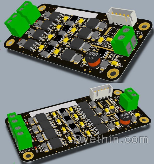
Design of High Current H-Bridge Motor Drive Circuit
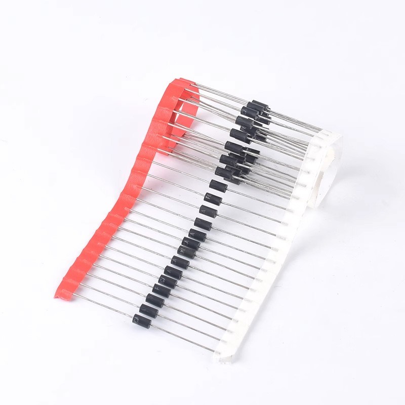
The working principle, key parameters, and selection of TVS
Understanding NAND Gate: The Universal Logic Gate in Digital Circuits
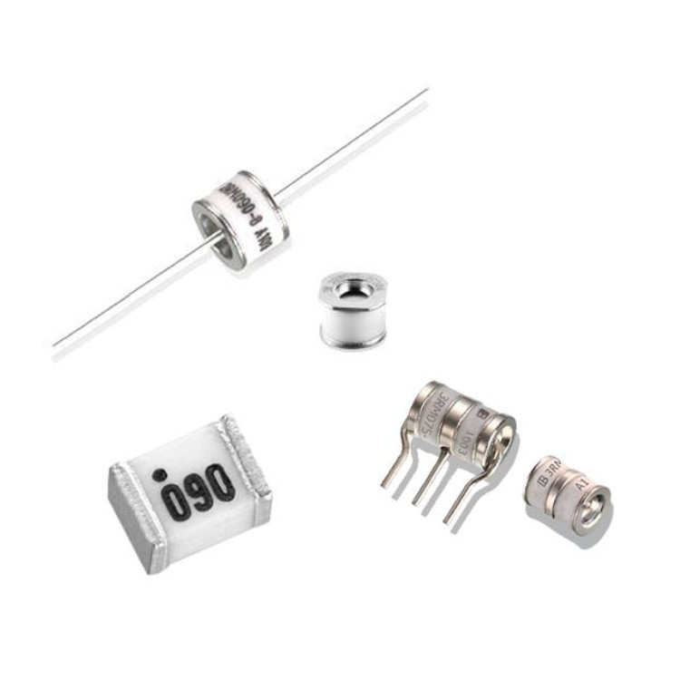
Gas Discharge Tube Symbols, Characteristics and Structure

-

-

-

-

-

-

-

-

-

littelfuse-inc
Polymeric PTC Resettable Fuse 6V 3.5 A Ih Surface Mount 1812 (4532 Metric), Concave