


The development history of oscilloscopes

The origins of electronic oscilloscopes are not easy to verify, so prehistoric times are divided by the operating characteristics of oscilloscopes. The edge trigger mode that we use most often today is probably even considered to be part of the basic functionality of an oscilloscope. In fact, before TEK 511, oscilloscopes did not have triggering capabilities. At this time, in order to display the waveform stably, the oscilloscope uses a technology called synchronous scanning.
The oscilloscope displays the waveform by performing a free sweep at a fixed frequency. To stabilize the waveform, it also has a simple comparator control to determine when to start scanning. However, due to the uncertainty of scanning time, the time axis of the oscilloscope is also unstable. This type of oscilloscope cannot make precise time measurements or observe non-periodic signals.
The starting point of the modern oscilloscope: Tektronix 511


In 1947, Tektronix released its first product: the Model 511 oscilloscope.
The biggest difference from his predecessors is that for the first time, he has a precise trigger system, which is actually the edge level trigger that every oscilloscope we can see today has. When the input waveform meets the polarity and threshold set by the trigger comparator, the oscilloscope starts to complete a scan according to the time set by the time base knob. In this way, the starting point of each sweep on the waveform can be determined by adjusting the trigger level. At the same time, the time of each sweep is known, and accurate time domain analysis of the measured signal can be performed by counting the grids on the screen. This is a huge leap, and its simple principle has become a necessary function of every oscilloscope today. It has to be said that it is the starting point of modern oscilloscopes.
Solid state, miniaturization
In the 1960s, when radio frequency semiconductor technology was advancing rapidly, companies like HP and TEK were in urgent need of high-performance solid-state amplifiers and various tube replacement devices. Since General Devices could not provide these components, they established their own R&D departments to meet domestic demand. . Since the military also has huge needs, the most important funds are naturally not a problem. For an oscilloscope, to increase the bandwidth, an oscilloscope tube with higher brightness, more precise focusing, and faster slew rate is needed. It also requires a high-speed preamplifier/Y-axis amplifier. Starting in the 1960s, all electronic tubes except oscilloscope tubes will be replaced by transistors and integrated circuits.

The Tektronix 555 oscilloscope, which was launched in late 1959, has a bandwidth of 30MHz and is made of a complete tube structure. It has huge power consumption and size. The bottom layer of the cart is its power box... Obviously such an oscilloscope is too much. So huge that it was practically unusable without his little car.


In the early 1960s, as the mass production problems of transistors were gradually solved, the process of solid-state instruments began. At this time, Tektronix launched the 321 oscilloscope. It is almost entirely made of transistors. In the early models, some of the tubes worked in the high-voltage area. Later models further replaced them with new transistors. Oscilloscopes at this stage were smaller and lighter. Finally, it can be taken off the cart, placed on the table, or easily moved to some special measurement sites.
The huge market demand stimulated them to develop all the accessories they needed, and also led to some other industrial projects, such as glass precision processing equipment and metal stamping equipment. By the late 1960s, Americans could already manufacture precision internally scored oscilloscope tubes. That is, the grid on the oscilloscope screen is engraved on the glass surface inside the oscilloscope tube. This results in smaller reading errors. However, all domestic oscilloscopes of the same era were engraved on acrylic sheets and placed in front of the fluorescent screen. They had different errors when viewed from different angles. In addition, there was no actual demand, and it was probably not until the late 1980s that a small number of internally scored oscilloscope tubes were produced, mainly for ultrasonic flaw detectors.

The two oscilloscope tubes I have on hand are from TEK 212 and 2430 oscilloscopes respectively. Both tubes are probably products from the 1970s and 1980s. They have detailed internal markings and can be clearly displayed when there is light (in the oscilloscope) Tungsten bulb backlight).

I still have a domestic 20M oscilloscope from the 1980s in my office. It has acrylic markings and is 1cm high from the screen of the oscilloscope, which brings about a very large reading error. Moreover, even if there is light, the markings are not visible. Not easy to see clearly.


A very small TEK 212 handheld analog oscilloscope, produced around the early 1980s, mainly supplied to the military. Bandwidth 0.5MHz.


The precise and beautiful accelerating electrodes in the TEK 2430 oscilloscope tube make the electron beam carry a very high energy, so that the oscilloscope can still have enough brightness for observation at high scanning speeds.
Okay, that’s a bit far. Come back and continue
High integration and modularization, automation, and data analysis
When did the integrated circuit enter the oscilloscope? I have indeed looked through a lot of information and it is difficult to determine.
However, our company once had a Tektronix 485 that was left over from its predecessors. It was launched in 1972. The company's current one was produced around 1978. Its bandwidth was 350MHz, which was beyond the reach of domestic products at the time. And the interior is very complex and the manufacturing process is quite sophisticated. Unfortunately, one day when I was playing with it, the screen suddenly went black and the fan stopped spinning. I suspect there is a problem with the switching power supply (yes, switching power supplies were already used in 1972). Then it was dismantled on site to prepare for maintenance. When it was disassembled, it was found that it was too complicated. The entire machine was wrapped inside and out by a PCB board, with the power supply in the center... So I took some hasty photos and put it back together. Back to the warehouse to sleep. Okay, no more nonsense, picture above:

Still can take a photo of the time when the phone was turned on

Nice panel, some buttons are backlit with tungsten bulbs.

From the port on the rear of the machine, it can be seen that there were already active probes in this period: it has two active probe power supply interfaces.

Remove the screws at the back and pull out the casing. It’s all densely packed with boards.

Product inspection signature on oscilloscope tube.

A peculiar integrated circuit customized by TEK at that time.

There are a lot of... input channel parts, which are also very complicated.

I collected some integrated circuits in my spare time, and the strange-looking one in the middle is TEK's own customized product. To our technical staff at the time, these things were like reading from heaven, and it was difficult to guess their specific uses. The further emergence of integrated circuits and microprocessors has opened up a good way for the automation of oscilloscopes. As the boss, Tektronix will naturally not let go of this opportunity to open up his imagination~


In the mid-1970s, all conditions were met and the time was ripe. Tektronix launched the 7000 series modular oscilloscope. Various modules were installed in a host display unit to define various functions of the instrument.


And it has a wide variety of modules...
You can see here for details, there are too many. For example, the horizontal and vertical modules required by the oscilloscope, the TDR module that intersects the frequency domain and the time domain, the frequency meter required by the radio frequency, and the spectrum analyzer module. The logic analyzer module required for digital circuit verification at that time....
Of course, no matter how much he modified it, he was still an analog oscilloscope. Analog oscilloscopes have many inconveniences, such as low bandwidth and inability to store. In the 1970s when high-speed digital-to-analog converters were not yet developed, high-energy physics experiments and measurements of microwave and radar systems urgently needed analog oscilloscopes with high bandwidth and storage capabilities. As a result, some real black technology products were produced (definitely different from those promoted by Ximi). Let’s talk about bandwidth first. For conventional analog oscilloscopes, that is, the kind that uses human eyes to see the screen. The highest record holder is the product of Japan’s Iwasaki Company (probably from the late 1980s) (I really don’t remember the model). Its bandwidth is as high as 470MHz! In the 1980s, Tektronix's products could actually only reach 400MHz (type 2467B). Since the display area of the oscilloscope tube of an ordinary desktop oscilloscope is large and the electron beam has a long stroke, the Y-axis driving capability cannot be increased without limit, thus limiting the overall bandwidth of the oscilloscope. Therefore, the bandwidth of some oscilloscope tubes can reach 600MHz. But it is difficult for the driving circuit to achieve this level.
Let’s talk about storage. Everyone knows that if an analog oscilloscope uses a single trigger, the waveform will sweep across the screen and disappear forever after a few milliseconds of afterglow. So technology emerged in two directions, one was the oscilloscope camera. This special camera is installed on the oscilloscope screen and keeps the shutter open. After the oscilloscope triggers, the shutter is closed to complete an exposure. This is a clever approach, but it requires developing the film every time you want to see the recorded waveforms.


Two oscilloscopes equipped with special cameras look a bit weird

Some adjustment options on the side of the C-53 camera, such as focus, aperture, shutter speed, film transport speed, etc.

A 1973 TEK brochure talks about the application of oscilloscope cameras.
Due to the cumbersome use of oscilloscope cameras, there is another technology, which is a memory oscilloscope tube. This kind of oscilloscope tube has a special storage grid installed behind the fluorescent screen, and there is a special readout electron gun inside the oscilloscope tube. After the main electron gun completes a scan, an electron gap is left on the grid. Then the readout electron gun is opened and the electron curtain is emitted uniformly to the storage grid. Part of it is blocked by the storage grid, and the other part is illuminated through the grid onto the fluorescent screen, and the stored waveform is reproduced.

From the simplified structural diagram of the storage oscilloscope tube, it can be seen that it has two additional FLOOD GUNS and a set of grids placed behind the fluorescent screen. However, such oscilloscopes can only be stored for a few minutes before they are obscured by electronic leakage. Later representative models include HP's 1741A model. This particular tube was also used in radar displays and RAM memory in early computers. This kind of oscilloscope tube requires more precise mechanical structure, and we can successfully produce tubes with low bandwidth in our country.

1741A oscilloscope

At this time, the oscilloscope is not connected to the probe, and the newly stored waveform is displayed on the screen.

After a few minutes, the waveform began to blur and eventually turned into a screen of green light.


1741A oscilloscope tube, from this angle you can see the readout electron gun with a white ceramic back cover.

This shows the low-speed scanning process in storage mode. First, the whole screen is illuminated with green light, which is the "erasure" of the oscilloscope, and then scanned one after another. The waveform still does not disappear after the first scan is completed.


For the SC-7 storage tube produced in my country in 1973, he replaced the phosphor with an electronic target for recording and reading data.
By the mid-1970s, electronic computers were also miniaturized, and they were increasingly used in the fields of measurement control and analysis. This requires electronic instruments that can record and digitize his measurement results. This seemed to be a problem for oscilloscopes, because it was not possible to produce high-bandwidth, high-sampling ADCs at the time. At this time, the Yankees used their crooked brains again. This time, Tektronix developed the 7912 (circa 1973) digitizer.

7912AD Digitizer

Advertising brochures for this type of device emphasize its ability to connect to computers.
He still uses analog oscilloscope tubes with a bandwidth of up to 1GHz, which if equivalent to the sampling rate of a digital oscilloscope is about 2Gsa. At the same time, it can provide digital waveform output with a dynamic range of approximately 12 bits. How did he do it? Tektronix uses scanning conversion tube technology (Scan conversation tube). This is a rather wonderful oscilloscope tube. It has two ends, one is the oscilloscope tube, which is responsible for waveform scanning, and the other side is the camera tube, which is used for image recording ( CCD has not yet been used in large quantities (previous products). In the center of the two tubes is the recording target. The oscilloscope tube emits a scanning electron beam to the recording target, which is then output by the camera tube and a low-speed AD converter to complete the recording of high-speed signals.

The SC108 scanning converter tube used in the 7912 digitizer.

This thing is so long that it can be called a screen-swiping artifact~
This is equivalent to an analog FIFO. Solving the technical problems at the time, this tube was used by Tektronix until the late 1980s to produce the SCD5000 series digitizers.

SCD5000 digitizer, this time he has an optional LCD screen to view the recorded waveforms.
Later, the same technology as the SCD5000 was launched by the Japanese Iwasaki company around 2001 as the TS-80000 series oscilloscopes, but the camera tube was replaced by a CCD. The same was true for the LeCroy LA354, which was actually OEMed by Iwasaki. At this time, Tektronix's digital oscilloscope had already crossed the 10Gsa sampling rate barrier and reached 20Gsa (TDS7404/7254).


The promotional description of the TS-80000 series briefly shows the structure of the scanning converter tube. In fact, it is a CCD that captures an oscilloscope, but the target surface of the oscilloscope is very small, making it easier to achieve high bandwidth.


TS-80000 with his screenshot. This LCD oscilloscope uses such a clever method to achieve the effect of an analog oscilloscope, and can also store and measure.

LA354 is actually made by Japanese.

In addition to digitizers, there were also some digital oscilloscopes with orthodox structures in the 1970s and 1980s. The pioneer of digital oscilloscopes is said to be the British company Nicolet, which manufactured the first digital oscilloscope and used magnetic tape to store data. However, the information is not very clear, and I can't find a picture of the first digital oscilloscope. The digital oscilloscope above is a product of Nicolet in the early 1980s. It is very fashionable to use an 8-inch floppy drive to store waveforms.
Segmentation, everyone gets what they need
After the chaotic 1970s, these manufacturers may have discovered that the starting point of modular equipment is good, but they are complex but not refined. Therefore, after long-term accumulation, oscilloscopes began to appear in various special subdivisions to meet different measurement needs.

For Tektronix, the general oscilloscope series is mainly the 2400 series. Most of them are analog oscilloscopes, but they have added a new AUTO function, that is, the oscilloscopes have some simple detection circuits inside that can test the frequency and Vpp of the input signal. In this way, you only need to input the signal to be measured into the oscilloscope, press the AUTO button, and soon the oscilloscope will automatically analyze and switch to the optimal range. This provides great convenience for user operations.

For the analysis of high-speed digital signals, Tektronix launched the DSA digital signal analyzer. In fact, this was the predecessor of the sampling oscilloscope used today. Its input channel is designed to be replaceable and can be replaced with an input sampling head or a TDR head. Bandwidth can reach tens of GHz.

During this period, in addition to producing analog storage oscilloscopes, HP's digital oscilloscopes were mainly used in automatic measurement systems. The instrument is completely controlled by the GPIB bus, so it has to be said that the front panel design is not very practical.
Just now, most of the Tektronix 2400 series are analog, but there is also a minority: Let’s talk about other analog FIFO storage oscilloscopes. In the 1980s, high-frequency semiconductor technology was very mature, so there was a method that used CCD to store waveforms. oscilloscope (yes, I am talking about the CCD of the camera, which was first developed for data storage, and the photosensitivity is only an incidental function). Representative models of this type of oscilloscope include Philips PM3310/3311 and Tektronix 2430/2431. The sampling rate can reach 200MHz. The CCD component is like a serial shift register for analog signals. It is driven by a high-speed sampling clock to quickly move the analog waveform in, and then driven by a low-speed readout clock, it is moved out to the ADC for digitization. It is also a smart approach, and the cost is much lower than that of scan converter tubes.


PM3310 oscilloscope, the last picture is its low-speed ADC, which has a sampling rate of about 12KHz. With the help of CCD memory, the sampling rate can reach 60M. However, I have compared the maintenance manual many times and still cannot determine which part of it or which IC the CCD is.
Fully digital, mixed-signal measurement
In the late 1980s, Tektronix and HP stopped producing analog oscilloscopes and devoted themselves to digital oscilloscopes. Among them, HP first launched the 54500 series, and the sampling rate was not too high, in the range of several hundred M.
However, it can meet the recording requirements for many applications. With the practical use of high sampling rate ADCs in the early 1990s, Tektronix also launched the very classic TDS500 series oscilloscopes, and defined the basic architecture of digital oscilloscopes in the next few decades.

In order to compete with Tektronix, HP launched the 54600 series whose panel operation is similar to that of a general-purpose oscilloscope.


Uncovered, the first generation ADC of the TDS500 series was produced from the early 1990s to about 1994. It has two cores. It is estimated that one is a sample/hold and the other is a pipe-line ADC.
For example, the TDS540 model has a bandwidth of 500 HMz and a real-time sampling rate of 1 GHz. This means that digital oscilloscopes are becoming truly practical and have good adaptability, and can replace analog oscilloscopes in many situations! However, these early high-performance digital oscilloscopes also faced the problem of too low waveform update rate, dozens to hundreds of times per second. They could not display the rich waveform information like analog oscilloscopes, and they could not have the afterglow effect that analog oscilloscopes can display. (If you have seen the CVBS video signal with a low-end oscilloscope, you should have a better understanding).

Use an analog oscilloscope to observe the video signal, which has subtle brightness changes, which is caused by the different scanning speeds of the signal itself. The synchronization period of the video signal is 50 or 60Hz, and the wide square area is the color scanning signal. Its frequency is much higher than the synchronization signal period. The Y-axis bandwidth of the analog oscilloscope is constant and is not affected by the scanning speed, so it can be precisely Display these waveforms.
Ordinary digital oscilloscopes generally use lower sampling rates under longer time bases. This results in aliasing in areas with dense waveforms, and in the end only some erroneous low-frequency aliased waveforms can be collected.

The left side is the effect of observing video signals with a general digital oscilloscope. A lot of details are lost. On the right is a digital phosphor oscilloscope. It is very close to the effect of an analog oscilloscope, which will be discussed later.
The current low-end domestic oscilloscopes are still like this. It is impossible to obtain the superimposed layer information of the waveform from the screen. When measuring the oscillation waveform with spikes in the switching power supply, the oscilloscope cannot record the details. Subtle glitch pulses are often not visible. This is because traditional oscilloscopes stop collecting every time they are triggered, and then the CPU starts to read out the sampling memory and update it to the video memory, which delays a lot of time. The oscilloscope may miss a large number of critical waveforms during data processing. In response to these problems, Tektronix began to launch the TDS500B/700A oscilloscope with instaVu technology in 1996. His method is relatively simple and violent. Compared with the sampling rate used in each time base of previous digital oscilloscopes, the instaVu oscilloscope uses a higher sampling rate to continuously collect waveforms to avoid aliasing, and superimposes them in RAM, and then every 30ms Update the screen so that a large number of superimposed waveforms can carry more incidental information, further approaching the effect of an analog oscilloscope. In 1997, an improved instaVu oscilloscope was released: TDS500C/700C. Compared with the previous generation, it could capture up to 400,000 waveforms per second! The analog oscilloscope is limited by the retrace time, which is equivalent to approximately 200,000 waveforms/second.

instaVu oscilloscope: It can display a large amount of superimposed waveform information, but it cannot provide three-dimensional data of the waveform.
At this time, the digital oscilloscope has only one last difficulty, which is the afterglow information that the analog oscilloscope can provide. The afterglow can tell us the frequency and speed of the waveform. For example, the analog oscilloscope cannot easily see the fast and steep rising edge of the square wave because the electron beam There is not much time to dwell on the edge and the phosphor cannot be fully excited. So Tektronix made further efforts and released the epoch-making TDS500D/700D series Digital Phosphor Oscilloscope in 1998. It is a further improvement of instaVu. It relies on the more powerful DPX fluorescence processor to superimpose waveforms while also calculating the overlap rate of each part of the waveform. Therefore, for the first time, a digital oscilloscope has a Z axis other than the X and Y axes, that is, The brightness axis, at this time, the digital oscilloscope can also be observed from a three-dimensional perspective.

The same waveform as shown above is displayed on the DPO oscilloscope, and the probability of signal occurrence is presented with different intensities.

The block diagram in the DPO brochure shows that it has parallel data processing capabilities. While waveforms are being collected and updated, the CPU and DSP can also continuously calculate parameters and refresh them on the screen. The DPX fluorescence processor is an independent working part.

TDS784D oscilloscope has 1G bandwidth and 4Gsa sampling rate. This was the last batch of products. It was shipped from the factory in 2001. It was equipped with the newly developed ADC and DPX controller. These components were later extended to the TDS5000 and 7000 series oscilloscopes.

motherboard

Collection board

CPU and an ASIC. His CPU is MOTOROLA MC68040, and the operating system is VxWorks

DPX controller on the acquisition board and extensive sample buffering. It can be seen that the process is still very complicated, and there is still a certain pressure on domestic copycats (in fact, 41 cannot do this 6). But for private enterprises, huge costs are required. Obviously there is no need for this, after all, the investment may not be rewarded.
Analog input problem


This is the front-end channel of the TDS500D series oscilloscope. Because this generation of front-end consumes a lot of power, it is built on a ceramic circuit board. And you can see that he used the most advanced laser adjustment technology at the time to ensure the consistency and stability of the final channel. I have also come across oscilloscope boards from HANTEK and RIGOL. Basically, without exception, there are several adjustable capacitors that need to be adjusted when calibrating the instrument.
The first-generation DPO oscilloscope only has 16 brightness levels. Compared with the almost unlimited brightness levels of the analog oscilloscope, it seems completely useless. In fact, it is already very good. Relying on the flexible measurement capabilities and powerful analysis performance of the digital oscilloscope, it is finally completely Replaces analog oscilloscopes.

A jittering signal

Testing a square wave, the edges look like an analog oscilloscope

There seems to be a metastable phenomenon.
In the same year, the bandwidth of Tektronix TDS694C digital oscilloscope reached 3GHz, and the real-time sampling rate exceeded the 10Gsa mark... In the new century, in addition to the Japanese, they also tinkered with scanning converter tubes in a short period of time, Tektronix, HP (already Agilent at this time) and LeCroy Comprehensively convert high-end oscilloscopes to the X86 platform, that is, convert the MC68000 series or ColdFire CPU used in the previous oscilloscopes to the PC platform, and have an auxiliary DSP to complete waveform analysis, further improving the measurement capabilities and measurement speed of the oscilloscope.


The TDS7054 oscilloscope now used by amateurs. It was launched by TEK in 2001 as a pc-based oscilloscope to replace the TDS700D series. It has better fluorescence performance, faster speed, more powerful analysis capabilities and more flexible communication ports.
The above is the main development route of Tektronix oscilloscopes in the 1990s, but this is not all of the 1990s. In the 1990s, some new concepts emerged in the field of oscilloscopes. At that time, they were limited by various technical limitations and failed to bring good practical results. However, these technologies have recently been put back on the market, further expanding the observation capabilities of oscilloscopes.
For example: mixed signal oscilloscope
The concept of mixed-signal oscilloscope was first proposed by HP Company. The main implementation method is to integrate the oscilloscope and logic analyzer into production, and the logic diagram and waveform diagram are displayed at the same time and reference each other. It plays a big role in the physical layer verification of digital-analog combination systems or digital systems.

This is supposed to be the first MSO with 16 logical (digital) channels. At the same time, this machine begins to use the latest MEGA ZOOM sampling technology, which is a competitive technology of DPO and can also bring the afterglow effect like an analog oscilloscope. So? What about before MSO?

Before HP launched the MSO, we also had such a Mars-level product - the TLS216. It was an oscilloscope with 16 analog channels... The Tektronix tube was called LogicScope. Specifically, it should be a monster designed using the TDS500 framework after the successful release of the TDS500 series architecture in 1992. He has a sampling rate of 2Gsa but it is divided equally by 16 channels. In addition, it has no protocol analysis capabilities, and the screen resolution is only VGA level. As a result, he was a complete failure. However, he provided HP with a good idea for designing MSO - that is, digital and analog should be separated, and protocol analysis capabilities should be added instead of pursuing a large number of analog channels.
New Century: Mixed Domain Analysis
Of course, it goes without saying that in the new century, the bandwidth and sampling rate of oscilloscopes have not stopped growing. In addition, some oscilloscopes have also added functions other than time domain measurement. For example, MSO can analyze the status and timing of logic signals.
The further MDO mixed domain oscilloscope adds a wideband spectrum analyzer, allowing the oscilloscope to re-examine the signal from the perspective of time domain/frequency domain/modulation domain, opening up a new world for measurement personnel (however, with such an NB oscilloscope, I I can’t afford it, so the detailed review, disassembly and pictures above are exempt.)
Having said so much, I actually want to use actual equipment to see how the predecessors have come one step at a time. Some of these transitional technologies have long since been phased out and forgotten. But looking back at these technologies, the light of wisdom still shines.
To put it bluntly, in addition to hard work, imagination and a lot of money are also very important. It can be seen that these historical products may not be successful, but they have brought a lot of technical accumulation. In addition, due to space limitations, more interesting equipment cannot be fully Write it out and send some pictures:


This is TEK 222. This thing is slightly larger than ip5s and is a 10MHz handheld digital oscilloscope. It is a product of the 1980s, and it has two channels that are isolated from each other. You can see from the picture that he used a magnetic isolator.
Let’s briefly talk about the technical reasons that lead to monopoly.
Materials and device materials rely heavily on the industrial base
The high-speed ADCs in high-end oscilloscopes are not made of conventional silicon materials. Some are made of gallium arsenide, indium phosphide, etc., which are relatively advanced. China is making up for its efforts in silicon materials for consumer electronics. That one is large in volume, but this one has not kept up.
High-speed ADC is not only used in oscilloscopes, but also in missile attitude, infrared night vision, tracking and aiming, etc. Everyone knows the military restrictions, so they are relatively strict. There is a legend that a certain unit bought someone else's high-end oscilloscope, disassembled a few ADCs, and threw away the rest, which became a joke.
In addition, not only the ADC, but also the FPGA required in the oscilloscope can only be produced by a few companies, all of which are in the United States. The best company in China is not well run and seems to be reorganizing. I have used it and it screwed me up once. It went bankrupt just after the product was completed. I am very sad. π_π Now FPGA is not the most serious bottleneck, but ADC It is possible to make it domestically, but the possibility of FPGA is very small. It is restricted by patents and technical difficulties. Although FPGA has achieved an amazing growth rate in recent years, the domestic technology is too immature. If you give it a chance to choose its devices, it will be fierce. It breaks your heart...
2. There are few electronic technical talents and little technical accumulation.
The great masters all know that the quantity and quality of education in our country is unsatisfactory. Overseas, it has been almost a hundred years since we accumulated technology from electronic tubes to transistors. We all have to follow the path they took, and we have to change the copycats and understand the principles. This will take time.
The reality is that there is not much time left for the Chinese team→_→Few of us understand circuits, especially analog circuits. For example, oscilloscope signal chain adjustment, triggering, and clock distribution are difficult. Because the instrument is not large in size, the devices can only be borrowed from other fields, such as communications. They cannot be developed independently and cannot afford the cost. Therefore, the signal chain has to be adjusted. Most of the time, tubes are used. I don’t know if there is any. How many Zhihu masters can build a broadband program-controlled PGA using tubes? If you can build it, please see the next article.
3. Labor is too expensive
Another difficulty with oscilloscopes is the algorithm. This is the highest pursuit of an oscilloscope. Whether it is simply calculating rms, filtering, or creating afterglow, pursuing the waveform refresh rate, this algorithm is implemented on FPGA. FPGA engineers are very expensive, compared with hardware. It is much more expensive. Some mature and capable algorithm engineers can pay up to the upper limit of housing provident fund in Beijing. Mature hardware engineers may need at least three to five years of work experience, and their salary is only a little over 10,000, which is not as good as the Internet entry salary.
The global electrical measuring instrument market has a capacity of approximately 30 to 40 billion, and oscilloscopes do not cost much at all. The market share of the entire domestic oscilloscope manufacturers is roughly estimated to be less than 2% (no data support). How much money can be used to support R&D costs? It cannot be said that the company I work for, the company with the second largest domestic market share, only has sales in the tens of millions, and its gross profit in the low-end market is less than 50%. Therefore, those who make oscilloscopes do it for the sake of sentiment, whether it is a company or an individual.
Articles you may also like
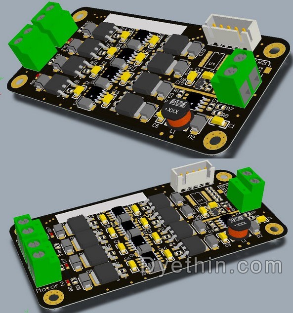
Design of High Current H-Bridge Motor Drive Circuit
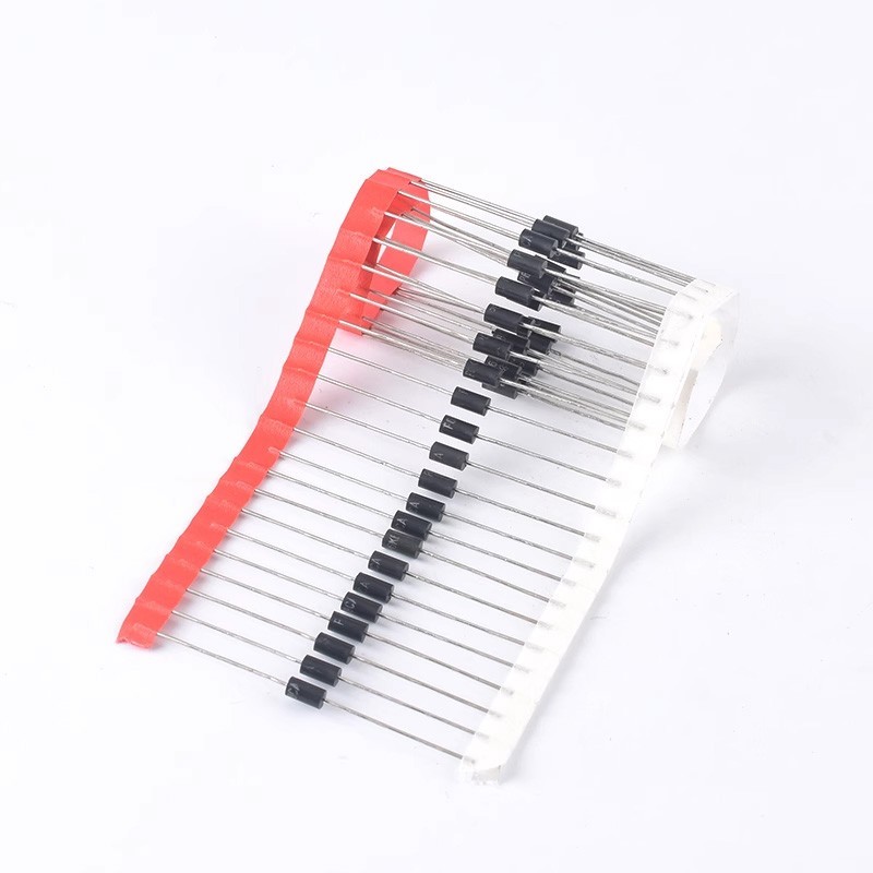
The working principle, key parameters, and selection of TVS
Understanding NAND Gate: The Universal Logic Gate in Digital Circuits
What is ESD and how to layout the ESD protection circuit PCB


