


How to choose a chip for board-level power supply?
Board-Level Power Supply Overview
When people are doing board-level power supply design, they often have an inertial thinking:
Either choose the power chip you have used before to build the circuit;
Either directly choose some existing modules in the company or laboratory;
But the power supply device you choose is likely not suitable for your usage scenario, which will cause many problems.
Classics are not necessarily the best, classics sometimes become outdated!
Of course, the design of board-level power supplies is a huge project, and it is difficult to cover it all at once, so this time I will only give a brief introduction to the four board-level power supplies that are commonly used when making preliminary designs for power supplies.
Voltage Reference Basics
REF voltage reference source
Voltage reference, most people will subconsciously ignore it when designing, thinking that any power supply can be used as the voltage reference REF.
Let’s first talk about why the voltage reference REF is used?
This has to mention the concept of signal link:

The most important links in the signal chain, ADC and DAC, need to use a voltage reference, which is also what we often call the reference voltage.
You can simply understand that the signal link for embedded systems is like the five human senses (vision, smell, hearing...), which accept various signals from the environment or nature, but many of the signals in nature are analog quantities. , but our CPU can only recognize digital signals, so what should we do?
Don't be afraid, we can convert analog signals into digital signals through ADC.
This conversion process requires the existence of the reference voltage REF.
Therefore, our requirements for this voltage reference are very high: precision, stability, reliability, low noise, and constant.
Key REF Parameters
Classification
Parallel type: use diodes or Zener tubes.

Series type: Use a unique chip, give it a voltage, and it gives you a stable reference voltage output.

So what parameter indicators do these parameter benchmarks have that we need to pay attention to when designing?
LDO Design Risks
Low noise
Let me ask a question first: Why can’t the high-precision ADC achieve the desired number of sampling bits?
Whether it's the chip's built-in or external ADC sampling, you can achieve the accuracy described in the data sheet.
why is that? A large part of the reason is noise from the reference voltage.
For example, there is a 24-bit sampling chip. When the reference voltage is 3.3V, its minimum division is as follows:

If I choose a REF chip 3325 at this time, its noise parameters are as shown on the right side of the picture above.
The reference output is 2.5V, the output current is 1mA (because it is used as a reference voltage, the output current does not need to be too large), and there is 70μV noise.
Obviously, your sampling accuracy can only reach 16 bits this time.
Initial voltage accuracy/temperature stability/long-term drift
I put these three parameters together and say
Before talking, you can download this instruction manual:
LTC6655_PDF_Datasheet_Datasheet_Specification

After opening, look at the first page:

High accuracy determines the initial voltage accuracy;
Low drift determines temperature stability;
Long-term drift refers to the change in voltage over time.
Quiescent Current
In fact, for sampling circuits, the smaller the quiescent current, the better, because an external device may want to work normally for one or two years, and if you want to reduce power consumption, of course, the smaller the quiescent current, the better.

Summary
In summary, when selecting a voltage reference source, you must follow the following requirements:
1. First of all, you need to clarify the accuracy and minimum division required for your ADC sampling;
2. Consider your working environment and temperature stability to calculate this error and make sure it is within the range you can bear.
3. The rest is just as long as the noise, initial accuracy and stable performance meet the requirements.
LDO
LDO can be said to be the simplest circuit for entry-level power supply design, but simplicity does not mean no risk.
Risk 1: Temperature rise of the chip
Output current capability, minimum voltage difference of the chip, actual operating pressure difference, and package thermal resistance are all relevant parameters that affect the temperature rise of the chip.

Risk 2: Transient response
In fact, this should be said to be a parameter of the LDO chip, or a picture in the manual.

Transient Response: You can pay attention to the data manuals of some poor-quality 1117 chips. Few manufacturers dare to put this test record on them.
Risk three: power consumption
When it comes to power consumption, we have to talk about quiescent current. The following is a comparison chart of four 1117 chips:

Of course, this is different from the voltage reference source. The smaller the quiescent current, the better, because the driving current of the connected load must be taken into consideration, so it must be considered comprehensively.
Buck and Boost Basics
Buck/Boost
Comparison of three types of DC/DC switching power supplies:

Difference 1: Look at the inductance value
The inductance value of 1 is 47μH, while that of 2 only requires 2.2μH
For the same current, my inductance value is only one-tenth of yours, and the volume can be greatly reduced;
Secondly, the larger the inductance value means that the current has to go around many times, causing a large copper loss.
Difference 2: Look at the output capacitor
2 and 3 are obviously much smaller than the capacitance value of 1.
Difference 3: Look at the floor area
The difference is even greater. 2 and 3 occupy very little space.
Difference 4: Whether there is an external freewheeling diode
Nowadays, most new DC/DC peripheral switching circuits no longer require diodes, but use MOS tubes built into the chip instead. We call this method synchronous rectification.
The old method that requires external diodes is called asynchronous rectification.

Switching Frequency and Efficiency
Some parameters that I usually don’t pay attention to
Switching frequency and conversion efficiency
These two parameters are enemies that need to be balanced.

Let’s first talk about why there are two indicators: switching frequency and conversion efficiency. In other words, what are the benefits of these two indicators or how can they be easily affected?
Adjustable frequency: By matching the resistance and capacitance values of the external circuit, the frequency can be adjusted to obtain the following benefits.
The higher the frequency, the greater the switching losses and dominate. When the frequency is low, the inductance and capacitance will increase.

Ripple and EMI Design
Ripple and EMI
In the past, we always talked about ripple, but we never explained how ripple comes from, so I will focus on it here.
The picture below is a very typical Buck circuit. The basic principle of this type of circuit is: the switching of the switching tube and the release of energy from the energy storage inductor.

When the upper tube is turned on, the current follows the blue route, forming a loop through the inductor and load.
When the upper tube is turned off and the lower tube is turned on, the current in the inductor cannot change suddenly, so the current will follow the green line.

The down tube here is similar to the role of the freewheeling diode in the past. It is the path for the inductor L to release its own energy.
So have you ever wondered why MOS tubes are now used to replace the previous freewheeling diodes?
Because the voltage difference of the diode is very large, and the freewheeling internal resistance of the MOS tube is very low, the efficiency is improved a lot after replacement.
Our parasitic inductance, the Lparasitic in the picture, is not so lucky.
Sources of parasitic inductance: PCB traces, chip internal bond lines, capacitor parasitic inductance, MOSFET internal traces
With high di/dt, the Hot Loop is the red loop. The larger this value is, the greater the impact on EMI and noise.
How to solve the problem of ripple and EMI?
Design 1: Give the chip two Vin and two capacitors to form two opposite current loops so that the generated magnetic lines of force cancel each other out.

Design 2: Improve packaging to reduce parasitic inductance.

Buck maximum duty cycle

Boost output isolation

Articles you may also like
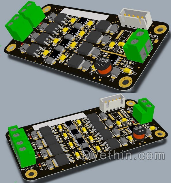
Design of High Current H-Bridge Motor Drive Circuit
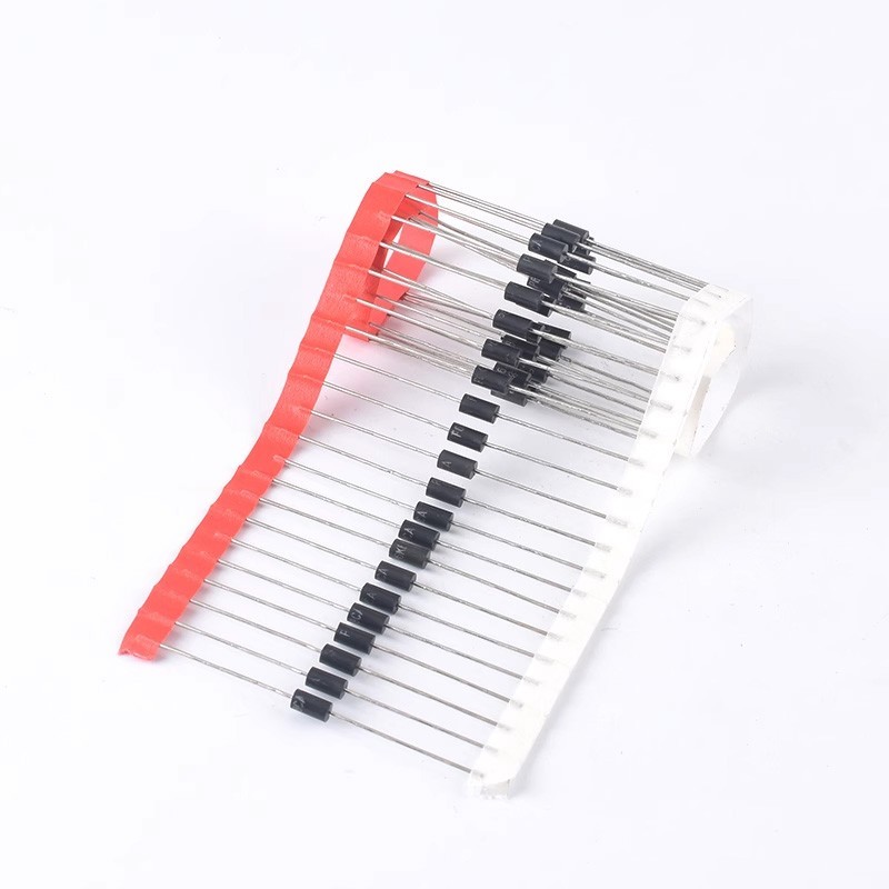
The working principle, key parameters, and selection of TVS
Understanding NAND Gate: The Universal Logic Gate in Digital Circuits
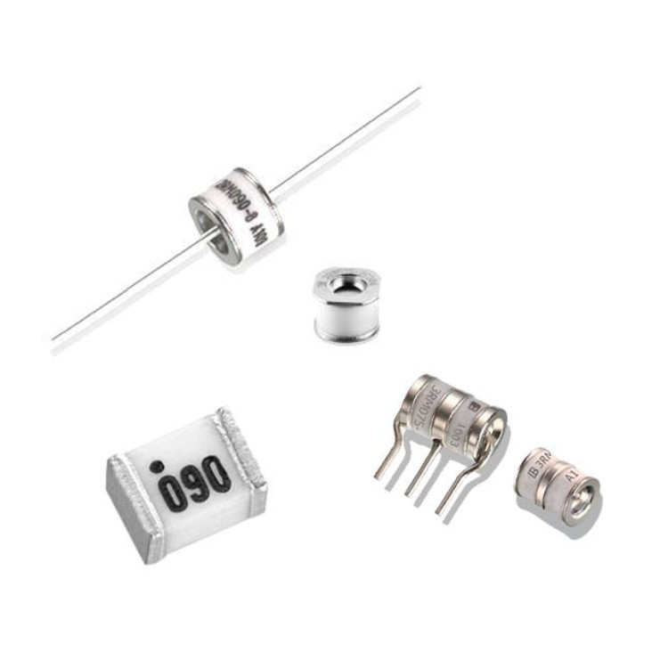
Gas Discharge Tube Symbols, Characteristics and Structure

-

-

-

-

-

-

-

omron-electronics-inc-emc-div
General Purpose Relays SPST-NO (1 Form A) 8 A 24VDC
-

-
