


- Startseite
- Blogs
- Basic knowledge
- Why do mosfet tubes always get hot?
Why do mosfet tubes always get hot?

Why is the power MOSFET always damaged?
Recently, they participated in smart car competitions and produced and debugged their wireless power transmission module for the debugging of energy-saving group car models. Compared with digital and analog circuits, this high-frequency, high-power analog circuit, although seemingly simple, has higher requirements in circuit design, device selection, debugging methods, etc., and requires a thorough understanding of basic physical principles and device characteristics. Have more in-depth knowledge. Now many universities have re-adjusted the order of electronic teaching according to the difficulty of the course, and teach in the following order from easy to difficult:

Question: May I ask teacher, we directly use CSD18532KCS for the power MOSFET tube of the transmitting module of the energy-saving group, and the peak-to-peak value at point A cannot reach 200V at all. When adjusting the frequency of the input gate, the frequency is adjusted too high and the MOSFET tube is damaged. Burned,. . Is there any suitable model for this MOSFET tube?
Reply: MOSFET tubes can use high-frequency MOSFET tubes such as T254. For the amplitude of the output signal to meet the design requirements, the following conditions need to be met:
1) L, Cs, and Cp each meet the half-cycle resonance condition at 640kHz;
2) The ratio of Cs/Cp should be the ratio recommended in the public account;
High frequency MOSFET tube
Since the signal amplitude is very high, please select the resonant high-frequency capacitor carefully. Ordinary capacitors will burn out quickly. In order to achieve the maximum output power of 50W, in the actual competition wireless module, two MOSFET tubes were used in parallel, and a good radiator and temperature protection switch were added.
For example, the following Class E 50W wireless power transmission board uses two MOSFET tubes connected in parallel to output high-frequency power signals.

Question: Hello teacher! I built a transmitter circuit for a class e power amplifier in the past two days. I used a 24.6uh coil. Cs is 2.2nf and Cp is 3.3nf. After calculation, the average of the two resonant frequencies is 764khz, so I used md1211 to give a 5v The square wave is powered by 10v on the choke coil. As a result, the frequency of the waveform resonating from the coil is 2.3mhz and the amplitude is only 960mv. See the picture below. Why is this?
Reply: This is indeed an interesting waveform. But just from the situation you described, I cannot help you locate the exact cause of this problem from the many possible error traps.
Since it is used to stimulate oscillation, the fundamental frequency of the output signal should be the same as the frequency of the excitation signal. If the frequency of the output signal you measure is different from the excitation signal, you can check separately whether the frequency, amplitude, and output MOSFET tube of the excitation signal are normal, whether the components in the resonant circuit are intact, whether the connecting circuits are reliably connected, etc.

Reasons why MOSFET becomes hot
Question: Teacher, I have replaced the transmitter power MOSFET tube with AOT254L and connected the resonant coil. When applying 24v DC voltage, the 24v does not change at first and the current slowly rises, but after a while the voltage still drops, and then The Mosfet tube is super hot. I would like to ask what is the reason for this? Also, the inductance value is measured without instruments. I want to make a more accurate measurement. Is there any good way? Thank you, teacher.

After the MOSFET tube became hot, I used an oscilloscope to measure the waveform at both ends of the inductor without adding a coil. It was a straight line swinging left and right. I tried it twice and the MOSFET tube heated up in the same way. The capacitance value I used was as shown in the figure. The same thing, the withstand voltage value is 50v, 100v, but I have tested it and there is no breakdown. Now I am a little confused. I have tried it many times. The Mosfet tube has been changed, the inductor has been changed, and the capacitor has also been changed. I would like to ask Zhuo Zhuo The teacher helps to find out the reason.
Reply: I guess the problem may be in the capacitor you are using. Check whether the capacitor is hot. 2. If you have an oscilloscope, observe the waveform of the oscillation signal to see if it is symmetrical. Compare the waveform at resonance given in the tweet.
The following waveform is the waveform of the D-pole voltage (blue) of the Class E high-frequency output MOSFET tube and the output resonant coil (pink) when the output power is from 0.5W to 20W. Due to the influence of voltage doubler rectification in the wireless receiving circuit, it can be seen that when the power is turned on, the output waveform will appear:
(1) The amplitude is reduced;
(2) High-frequency oscillation appears in the second half of the pulse;
(3) The symmetry of the waveform is reduced.

When working in the high-frequency output stage, it is necessary to ensure that the output coil is reliably connected to the Class E power output port. If the coil is disconnected, the microcontroller needs to be able to turn off the output signal in time according to the collected waveform distortion, otherwise it will easily burn out the output power tube.
The following waveform is collected by the microcontroller and the output waveform is displayed on the LCD. At the same time, the harmonic ratio of the waveform is calculated. It can be seen that under resonance, as the output power increases, although the amplitude and shape of the waveform change to a certain extent, the proportion of harmonics (2nd, 3rd, and 4th harmonics) always remains at about 15%-18%. If the harmonic ratio exceeds 25% and above, the power output needs to be stopped. Because the efficiency of the Class E power emitter is reduced too much at this time, it is easy to burn out the output MOSFET tube.

Question: Teacher, the wireless transmitting and receiving circuit I made has a resonant voltage of 1000V during debugging. Is this normal?
Reply: In high-frequency and high-power circuits, resonant high voltage may occur. However, in circuits, this situation needs to be avoided. The occurrence of resonance can easily cause voltage breakdown of the resonant circuit components (especially the resonant capacitor), increase in losses, etc.
MOSFET voltage waveform
In the receiving circuit recommended in the tweets and competition rules, the receiving coil is connected in series with a voltage doubler or full-wave rectifier circuit. At this time, the capacitor is not used to resonate with the receiving coil, but to compensate for the leakage inductance of the receiving loop. It compensates the leakage inductance outside the coupling of the transmitting coil and the receiving coil to further reduce the internal resistance of the receiving loop and increase the output power.

Articles you may also like
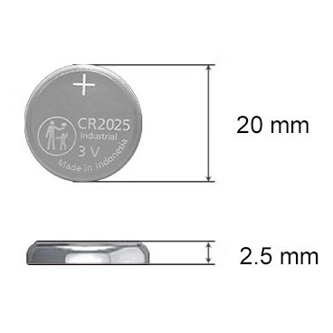
CR2025 Battery: Equivalent, Specifications and Replacements
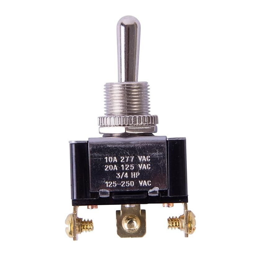
Understanding Toggle Switches: A Comprehensive Guide

CR1632 vs CR2032: Are CR1632 and CR2032 battery equivalent?

CR1616 Battery Equivalent: Best Replacement Guide


