


- Strona główna
- Blogs
- Basic knowledge
- Troubleshooting of high power LED driver circuit
Troubleshooting of high power LED driver circuit
Sharing on troubleshooting high power LED PCB

High power LED PCB board
The power supply comes from a 24 VDC power supply. For testing purposes, a 30A adjustable power supply is used here, with a total of 100 LEDs and 11 different types of LEDs.

24VDC main input power supply
The power supply is filtered through fuses and capacitors, and the TVS diode prevents transients.
Design background
The most challenging part of this design is determining how to better drive LEDs. We need to fully control the brightness and minimize the heat generated.
The first option is to use a constant current LED dedicated driver, including a linear driver and a driver with an internal switch stabilizer. The first thing to rule out is linear drivers.
The driving current of the LED light string is about 1A, and some light strings only have 4 LEDs. For example, for a forward voltage of 3V, the driver dissipation is required (24V – 3V * 4) * 1A=12 W.
The power of 12 watts far exceeds the power that most drives can safely dissipate.
The second option is to use a separate switch driver for each chain. The advantage of this method is that each chain can operate very efficiently, as most modern switch regulators have an efficiency of over 80%.
The advantage of doing this is that since we use a 24 VDC power supply, we cannot concentrate all 11 LED models on 11 wires. Therefore, 18 different wires are required. Due to the large size of the PCB, it is not very good to have 18 switch regulators switch to high-power loads.
Combining Linear and Switching Power Supplies
Finally, it was decided to use a hybrid method to design multiple twisted wires, resulting in a few volts of headroom on a 24V power supply.
For example, the forward voltage of an LED is 2.8V. When using 8 of them on a single strand, we only need to reduce 24V - (8 * 2.8V)=1.6V. When driven by 1A, the dissipated power is only 1.6W, using one or two high-power resistors.
Overall, we can drive nine LED strings in this way, which is almost half of the required number of strings. The following figure shows an example of two chains.

Long strand wire directly driven by 24VDC guide rail
The low side N-channel MOSFET drives each LED string, while the dedicated MOSFET driver turns on/off the MOSFE.
Then, use a switch regulator to divide the 24V power rail into three additional power rails. Here, 7V, 13V, and 16V are selected. With these specific voltages, the remaining shorter strands can be driven in the same way as the longer strands, and one or two resistors can be used to dissipate excess power. This method is good because we can directly PWM all strands, which will provide the same response and also benefit from the high efficiency of switching topology.
 reduces the voltage rail to a specific voltage, allowing for linear driving of LEDs from the new rail")
The switch regulator (RT8279) reduces the voltage rail to a specific voltage, allowing for linear driving of LEDs from the new rail
As shown in the above figure, the switch regulator uses a CLC input filter, which ensures that high-frequency switch noise does not leave the regulator and couple with other things on the PCB. These power rails also have a large number of output capacitors.
As shown in the following figure, this new guide rail supplies power to other LEDs with shorter strands.

The new 13V rail drives the LED on the shorter chain, and the new voltage rail reduces power loss on the resistor
Preliminary testing
Firstly, test each wire individually at full power, and then test it using a PWM signal - initially at 100Hz. Starting with a duty cycle of approximately 10% for all stock lines, then slowly increasing.
Once we reach 20%, our power supply begins to experience various errors and problems, basically entering an overvoltage locking state, and then completely shutting down.
Then we try to use a 100% duty cycle and start lowering it from there. Keep running well until the same problem occurs at 80%.

oscilloscope
When troubleshooting the circuit, the oscilloscope shows a significant voltage drop at the same frequency as the driving PWM signal.
Start troubleshooting
There is a problem with the main 24V input rail, so we will start troubleshooting the circuit from there. First, we will connect the oscilloscope to the input terminal of the PCB, and you can see a 3.5V Vpp signal with a sound frequency of 100Hz, which is the same as the frequency we drive.
Whenever the PWM pulse increases, the main voltage rail will drop by a few volts, and the voltage waveform precisely explains the reason for dissatisfaction.
Next, let's see if we can further isolate. Most of the complexity of this design lies in the switching regulator, and analysis suggests that the strands that caused the drop are those that pass through them. Therefore, we have closed all 24V lines and only implemented PWM control on the switch voltage regulator, which can eliminate problems on the railway. However, there is still a small voltage transient, which is not enough to cause power failure,
It is obvious that the problem lies in the native 24V wiring harness, but independent testing was still conducted on it. Sure enough, the oscilloscope showed an equally severe voltage drop.
Due to the use of MOS transistors to drive LEDs, when the PWM signal becomes high, a current surge of 1A will occur on each line, which is a large amount of current quickly provided for any power rail. The MOS transistor driver we use has a 100R resistor between its output and the MOS gate.
Changing this value will slow down or accelerate the conduction speed of MOS. This time, it changes the speed of current surges, so we will change the value from 100R to 1K, then 500K, or even 1M.
Although changing the gate resistance does solve the voltage sag problem, its conduction speed is very slow, so that the MOSFET remains in the linear region.
It essentially acts as a constant current amplifier, rather than a simple on/off switch. When driving MOSFETs like this, the power loss will be too large to dissipate.
Solution
Changing the PWM frequency to 20kHz reduced the voltage drop by more than half. The voltage drop is at the same driving frequency of 20kHz.
Then we tried 30 kHz, then 50 kHz, and the voltage drop on the oscilloscope was no longer significant.
The power supply will no longer have any problems driving the load. This issue has been 100% resolved in all work cycles with all LED light strings running.
The best solution is ultimately simple software changes!

Explanation of the plan
Now discussing why changing the PWM frequency solves the problem.
1. 100Hz frequency
● Fully charge the input battery.
● The first PWM signal turns on all LEDs simultaneously.
● The current surge completely depletes the current of the capacitor. This forces the circuit board to attempt to directly obtain current from the power supply.
● Due to the presence of inductance and resistance on the power lead, the PSU is unable to provide the current required for the motherboard.
T● he voltage on the circuit board drops until the supply can 'catch up' with energy demand.
● PWM cycle closed; All capacitors can be fully charged.
● repeat
2. 50kHz frequency
● The input capacitor is fully charged.
● The first PWM signal turns on all LEDs simultaneously.
● The current surge begins to deplete the capacitor.
● Before the capacitor is completely depleted, the PWM cycle will close, allowing the capacitor to recharge.
● repeat
As mentioned earlier, the wiring in the PSU lead can cause resistance and inductance between the PSU and the circuit board. At higher frequencies, I believe that the magnetic field generated by the inductor can remain constant while providing a current of 10+amperes.
When PWM is performed at a sufficiently high frequency, the PSU generates a constant 10 ampere current. When the frequency is 100Hz, it will see switches that cannot keep up.
Articles you may also like
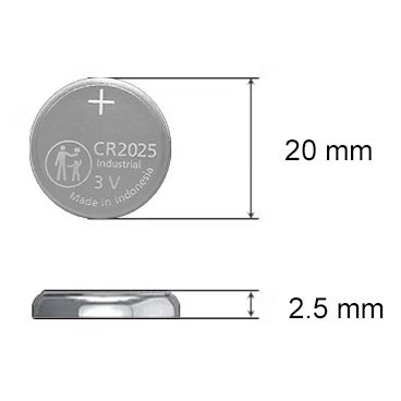
CR2025 Battery: Equivalent, Specifications and Replacements
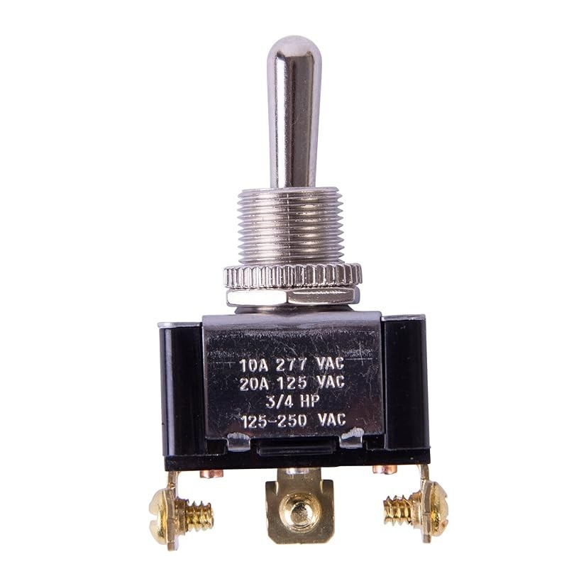
Understanding Toggle Switches: A Comprehensive Guide
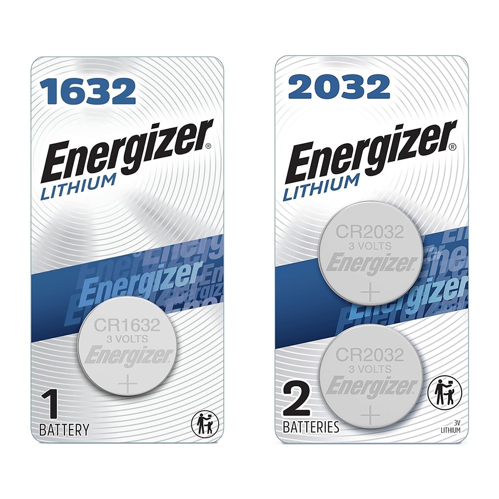
CR1632 vs CR2032: Are CR1632 and CR2032 battery equivalent?

CR1616 Battery Equivalent: Best Replacement Guide

-

-

-

-

-

-

-

-

-

qualcomm-rf360-a-qualcomm-tdk-joint-venture
Industrial router microcontroller chip 260-BGA