


- Startseite
- Blogs
- Basic knowledge
- How does a network transformer work?
How does a network transformer work?
In a wired LAN, servers, routers, hubs, computers and other devices are connected through Unshielded Twisted Paired, UTP. However, since these devices may be installed in different buildings, the longest distance can reach 100m. If at this time Directly connecting electronic devices in two places will cause many problems.
1. Different reference ground levels: An overly long network cable will cause the ground potential of the devices at both ends of the network cable to be different, forming a slowly changing voltage with an extremely low frequency. The slowly changing voltage will be directly added to the PHY chips of the devices at both ends (two grounds), thus Causes the PHY chip to be burned out.
2. Poor electromagnetic interference resistance: A nearly 100-meter network cable is equivalent to a very long antenna. External electromagnetic interference (including thousands of volts of lightning interference) will enter the network card through the network cable, which may cause bit errors in the transmitted data signal. In severe cases, it may even break down the PHY chip.
3. Strong external radiation: The electromagnetic radiation generated by switching power supplies and clock signal generators inside servers and other equipment will be emitted to the surrounding space through network cables, causing interference to other equipment.
4. Impedance mismatch: The characteristic impedance of cables and twisted pairs is fixed. In order to ensure signal integrity (SI), the internal resistance of the signal source, the load resistance and the characteristic impedance of the twisted pair need to be matched. Otherwise, both ends of the network cable must be matched. Reflections will occur due to impedance mismatch, which may cause bit errors in the transmitted data signal.
In order to solve the above problems, a device needs to be introduced between the UTP and PHY chips for signal coupling, high-voltage isolation, impedance matching, electromagnetic interference suppression, etc. This device is a network transformer.

Working principle
The three basic parts of a network transformer are: T piece (Transformer), K piece (Common mode Choke), and A piece (Center Tapped Auto-Transformer); according to different combination methods, network transformers are divided into: single T piece network transformer, T piece pieces + K pieces network transformer, T piece + three-wire through-ring K piece network transformer and T piece + K piece + A piece network transformer.
Single T-piece network transformer
As the name suggests, the single T-piece network transformer is composed of a 1:1 transformer. According to the principle of electromagnetic coupling of the transformer, when a balanced signal acts on a twisted pair (UTP), a signal of the same size can be induced losslessly on the primary side of the transformer, thereby realizing signal transmission.

In addition, the network transformer can also block EMI from propagating between its primary and secondary coils.
When EMI acts on a twisted pair (UTP), due to the characteristics of the twisted pair, the waveforms of the EMI voltage on Pin6 and Pin4 can be considered to be exactly the same, so the currents they cause in the upper and lower secondary coils are equal. , opposite directions, so the magnetic flux changes caused by the two currents in the magnetic ring cancel each other out; the magnetic flux change is zero, which means that the inductive reactance of the upper and lower secondary coils to the EMI signal is zero, so the EMI signal can be lossless The ground passes through the coil to the middle tap, and then discharges to the ground through the series circuit of R1 and C1.
In the same way, the EMI signal from inside the device will also be discharged to the ground through the middle tap of the primary coil and C2, thereby reducing the EMI amplitude emitted by the device through UTP.

T piece + K piece network transformer
Because non-ideal transformers have parasitic capacitance, part of the EMI signal will be coupled to the primary end of the transformer through the parasitic capacitance. Therefore, in order to further block EMI from propagating between the primary and secondary coils, a single T-piece network transformer can be used , and then connect a K piece (Common mode choke, common mode choke) in series to the primary or secondary side of the transformer. This is the T piece + K piece network transformer.
When the balance signal passes through the K piece, the currents in the upper and lower coils of the K piece are equal in magnitude and opposite in direction, that is, the magnetic flux changes caused by the two currents in the magnetic ring of the K piece cancel each other out; this means that the K piece has a negative impact on the balanced data signal. The inductive reactance presented is zero, so the data signal can be transmitted losslessly in the K-ware.

When the EMI signal passes through the K piece, the currents in the upper and lower coils of the K piece are equal in size and direction, that is, the magnetic flux changes caused by the two currents in the magnetic ring of the K piece are superimposed on each other, which means that the K piece presents a negative impact on the EMI signal. There is a certain inductive reactance, so the EMI signal will produce greater attenuation when it passes through the K piece. The inductance of K components to EMI signals is:
ZL=2 π f L
In the formula: f is the frequency of the EMI signal; L is the inductance of the K component (about 10uH).

Although the K component placed on the line side can better suppress EMI interference, due to the increased impedance of the common mode inductor, it will affect the 75R termination effect of the transformer center tap. Therefore, for voltage type PHY, common mode inductors are generally used. Network transformer on the PHY side; in addition, if POE is used, the common mode inductor on the line side will cause magnetic saturation due to the power supply current of POE, which greatly reduces the common mode suppression effect. Therefore, common mode inductors on the line side cannot be used in POE scenarios. transformer.
But for current-type PHY, the common-mode inductor cannot be placed on the PHY side. When the instantaneous current of the normal data signal passes through one of the coils or two coils, the magnetic flux change inside the K-piece magnetic ring is not zero, which means that the K-piece will produce a high impedance to the normal signal, thereby affecting the transmission of the normal signal.

T piece + three-wire ring K piece network transformer
For current-type PHY chips, placing the K piece on the PHY side will affect signal transmission, and placing the K piece on the UTP side will affect the impedance matching of the center tap. Therefore, in order to solve this problem, the designer designed a T piece + three-wire pass-through ring K-piece network transformer, the K-piece of this network transformer is obtained by winding three leads in parallel on the magnetic ring with the same number of turns.

When the T piece + three-wire through-ring K piece network transformer is used in a current-type PHY scenario, the instantaneous current of the normal data signal flows out from the Vcc terminal, passes through the middle coil, and then enters the PHY chip through the upper and lower coils, but the three-wire The total current in the ring-through K piece is always zero, that is, the total magnetic flux change is also zero, so the data signal can be transmitted losslessly in the three-wire ring-through K piece.

The disadvantage of the three-wire ring-through K piece is that EMI signals can also pass through without loss. When the common-mode EMI current passes through the three-wire ring-through K piece, in the same way, the total magnetic flux change in the upper, middle and lower coils of the three-wire ring-through K piece is zero, so it cannot attenuate the EMI signal.
T piece + K piece + A piece network transformer
If you want to place the K piece on the UTP side without affecting the impedance matching, you can add another autotransformer between the K piece and the UTP, thus forming a T piece + K piece + A piece network transformer.

When the balanced signal passes through the upper and lower coils of the autotransformer, the current directions are the same, that is, the magnetic flux changes caused by the two currents in the magnetic ring of part A are superimposed; this means that the inductive reactance of part A to the signal is very small. Large, it will not affect normal data transmission.

When the EMI signal passes through the upper and lower coils of the autotransformer, the currents are equal in magnitude and opposite in direction, so the magnetic flux changes they cause inside the magnetic ring of part A cancel each other out, which means that the inductive reactance of part A to the EMI signal is zero, two short wires can be used to replace the upper and lower coils, so the EMI signal will be discharged to the ground through the center tap and the R1-C1 series circuit, thus reducing the EMI amplitude (A) transmitted by UTP to the network card The principle of EMI leakage from the component is the same as that of the secondary coil of the T component).

Note: Although the K and A parts in the network transformer can block EMI from propagating between UTP and the network card, they also have a certain negative effect on the data voltage signal because both the K and A parts have parasitic and distribution parameters. . For example, there are inter-line capacitances between the two coils of Part K and Part A. These capacitors are connected in parallel at both ends of Ping6-Pin4. Parallel capacitors at the output or input end of the network transformer will definitely compress the frequency band of its high-frequency end. The narrowing of the frequency band of the network transformer will slow down the rising and falling edges of the data signal, ultimately resulting in a reduction in the transmission rate.
Therefore, it is enough to arrange one K piece and one A piece in the network transformer, or to arrange one K piece on the primary side and the secondary side of the T piece. If the number of K pieces or A pieces is increased, it will not only increase the production cost , will also reduce the data transmission rate.
Since the secondary coil of the T piece plays the role of the A piece, most network transformers currently on the market are composed of T pieces and K pieces.
Articles you may also like
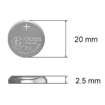
CR2025 Battery: Equivalent, Specifications and Replacements
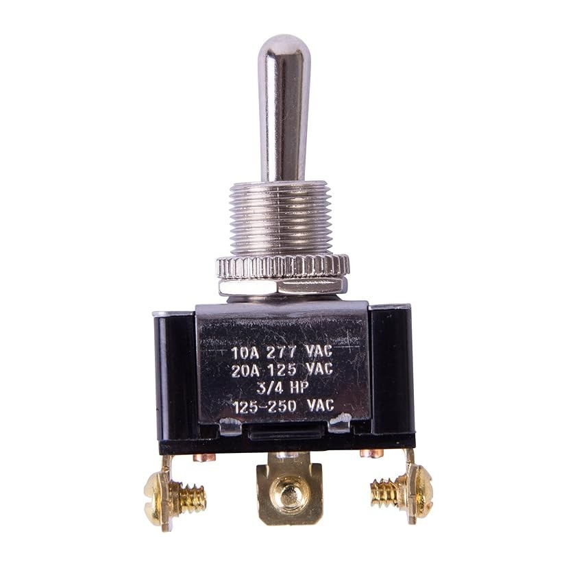
Understanding Toggle Switches: A Comprehensive Guide

CR1632 vs CR2032: Are CR1632 and CR2032 battery equivalent?

CR1616 Battery Equivalent: Best Replacement Guide


