


- Strona główna
- Blogs
- Basic knowledge
- Do you know how to use triode in circuits?
Do you know how to use triode in circuits?

Transistors have two working states: static and dynamic. The DC working state of the triode when no signal is added is called static. At this time, the current in each pole is called static current. The working current after adding AC signal to the triode is called dynamic operating current. At this time, the triode is in the AC working state, that is, dynamic.
A complete transistor circuit analysis has four steps: DC circuit analysis, AC circuit analysis, component and repair diagram identification.
1. DC circuit analysis method
The DC operating voltage is applied to each electrode of the triode mainly through two DC circuits: one is the DC circuit between the collector and emitter of the triode, and the other is the base DC circuit.
Through this step of analysis, we can figure out how the DC operating voltage is applied to the collector, base and emitter. As shown in the figure, it is a schematic diagram of the amplifier DC circuit analysis. For a single-stage amplifier, its DC circuit analysis mainly includes the three parts shown in the figure.

When analyzing a transistor DC circuit, since the capacitors in the circuit have DC blocking characteristics, they can be regarded as open circuits. In this way, the circuit shown in the above figure can be drawn as a DC equivalent circuit as shown in the figure below, and then use this equivalent circuit. DC circuit analysis of the circuit is quite simple.

2. AC circuit analysis method
AC circuit analysis is mainly the analysis of the transmission route of the AC signal, that is, where the signal is input into the amplifier, what components the signal passes through in this amplifier, and where the signal is finally output. As shown in the figure, it is a schematic diagram of AC signal transmission route analysis.

In addition, it is necessary to analyze what processing the signal has received during the transmission process, such as which link the signal is amplified, which link it is attenuated, which link it does not amplify or attenuate, whether the signal is compensated, etc.
The signal in the circuit above passes through C1, VT1, C2, VT2 and C3. C1, C2 and C3 are coupling capacitors. They do not amplify or attenuate the signal, but only play a coupling role in transmitting the signal to the lower circuit. VT1 and VT2 amplify the signal.
3. Component function analysis method
3.1 Component characteristics are key to circuit analysis
When analyzing the role of components in a circuit, it should be based on the main characteristics of the component. For example, a coupling capacitor allows AC signals to pass without loss while blocking the DC path. The theoretical basis for this analysis is the DC and AC blocking characteristics of the capacitor.
3.2 The specific role of components in the circuit
Each component in the circuit has its specific role. Usually one component plays one specific role. Of course, there are also components that play two roles in the circuit. In circuit analysis, it is required to understand the specific role of each component in the circuit.
3.3 Simplified analysis method of components
The analysis of the role of components can be simplified. After mastering the role of components in the circuit, it is not necessary to conduct detailed analysis of each component every time. For example, after understanding the role of coupling capacitors, it is not necessary to analyze every coupling capacitor. As shown in the figure, it is a schematic diagram of coupling capacitance analysis.

4. Repair diagram identification method
Repair diagram identification is a service for troubleshooting circuit faults. This diagram identification requires a complete understanding of the working principle of the circuit, otherwise it is meaningless. Because the fault phenomenon is clear, the repair diagrams during the troubleshooting process can be carried out by selecting the components in the circuit in a targeted manner, without the need to perform fault analysis on each component in the circuit.
During analysis, find out the main components in the circuit and assume that they have faults such as open circuit, short circuit, increased or decreased resistance, analyze the impact of such faults on DC circuits and AC circuits, and deduce the possible root causes of the faults.
The key to repairing diagrams is to find the key test points in the circuit:
4.1 Key test points of single-stage amplifier
As shown in the figure, the single-stage amplifier is mainly the critical test point of the triode.

The key test points of the transistor are used to measure the DC working voltage of the three electrodes. The collector is the first test point, followed by the base and the third is the emitter.
4.2 Key test points of integrated circuits
The most important key test points of integrated circuits are power supply pins, as well as input signal pins and output signal pins.
5. Transistor base bias circuit analysis method
The analysis of the base bias circuit of a triode is the most difficult. Mastering some circuit analysis methods can facilitate the analysis of the base bias circuit.
5.1 The first step in circuit analysis is to find the circuit symbol of the triode in the circuit, as shown in the figure, and then find the base in the triode circuit symbol. This is a key step in analyzing the base bias circuit.
5.2 The second step starts from the base and finds all the components connected to the base and the power terminal. As shown in the figure, RB1 in the circuit, and then finds all the components connected to the base and the ground. Such as RB2 in the circuit, these components form the main circuit of the base bias circuit.

After the Dyethin test and analysis of the above components connected to the base, it is necessary to distinguish which components may be components in the bias circuit. The resistor may form a bias circuit, and the capacitor has a DC blocking effect and is considered an open circuit. Therefore, when analyzing the base DC bias circuit, the capacitor does not need to be considered.
3. In the third step, after determining the components in the bias circuit, analyze the base current loop, as shown in the figure. The base current loop is: DC operating voltage VCC→bias resistor RB1→VT1 base→VT1 emitter→VT1 emitter resistor RE→ground.
6.Parameter explanation of triode
△ λ---Spectral half-width
△VF---Forward voltage drop difference
△Vz---voltage increment of voltage regulation range
av---voltage temperature coefficient
a---temperature coefficient
BV cer---base and emitter are connected in series with a resistor, CE junction breakdown voltage
BVcbo---emitter open circuit, breakdown voltage between collector and base
BVceo---base open circuit, CE junction breakdown voltage
BVces---Base and emitter short circuit CE junction breakdown voltage
BVebo---open collector EB junction breakdown voltage
Cib --- common base input capacitor
Cic---collector junction barrier capacitance
Cieo---common emitter open input capacitor
Cies---common emitter short circuit input capacitor
Cie --- common emitter input capacitance
Cjo/Cjn---junction capacitance change
Cjo---zero bias junction capacitance
Cjv---bias junction capacitance
Cj---junction (interelectrode) capacitance, indicating the total capacitance of the germanium detection diode under the specified bias voltage applied to both ends of the diode.
CL---load capacitance (external circuit parameters)
Cn---neutralizing capacitor (external circuit parameters)
Cob---common base output capacitor. In the base circuit, the output capacitance between the collector and the base
Coeo---common emitter open circuit output capacitor
Coe---common emitter output capacitance
Co---zero bias capacitor
Co---output capacitor
Cp---parallel capacitance (external circuit parameters)
Cre---common emitter feedback capacitor
Cs---case capacitor or package capacitor
CTC---capacitance temperature coefficient
CTV---voltage temperature coefficient. The ratio of the relative change of the stable voltage to the absolute change of the ambient temperature under the test current
Ct---total capacitance
Cvn---nominal capacitance
di/dt---critical rise rate of on-state current
dv/dt---critical rise rate of on-state voltage
D---duty cycle
ESB---secondary breakdown energy
fmax---the highest oscillation frequency. The operating frequency when the transistor power gain is equal to 1
fT---Characteristic frequency
f---frequency
h RE---common emitter static voltage feedback coefficient
hFE---common emitter quiescent current amplification factor
hfe---minimum signal total emission short-circuit voltage amplification factor
hIE---common emitter static input impedance
hie --- total emission of very small signal short circuit input impedance
hOE---common emitter static output conductance
hoe --- total emission of very small signal open circuit output admittance
hre---Total very small signal open circuit voltage feedback coefficient
IAGC---forward automatic control current
IB2---Base modulation current in unijunction transistor
IBM---the maximum value of DC current that can continuously pass through the base within the range of the collector's allowed power dissipation, or the maximum average value of AC current
IB---the average value of base DC current or AC current
Icbo---the base is grounded, the emitter is open to ground, the reverse cut-off current between the collector and the base under the specified VCB reverse voltage condition
Iceo---the emitter is grounded, the base is open to ground, and under the specified reverse voltage VCE condition, the reverse cut-off current between the collector and the emitter
Icer---a series resistor R between the base and the emitter. When the voltage VCE between the collector and the emitter is a specified value, the reverse cut-off current between the collector and the emitter is
Ices---the emitter is grounded, the base is short-circuited to ground, and under the specified reverse voltage VCE condition, the reverse cut-off current between the collector and the emitter
Icex---The emitter is grounded, a specified bias voltage is applied between the base and the emitter, and under the specified reverse bias voltage VCE, the reverse cut-off current between the collector and the emitter
ICMP---collector maximum allowable pulse current
ICM---the maximum allowable current of the collector or the maximum average value of the AC current.
ICM---Maximum output average current
Ic---the average value of collector DC current or AC current
IDR---Thyristor off-state average repetitive current
ID---dark current
IEB10---Reverse current between the emitter and the first base in a double-base unijunction transistor
IEB20---emitter current in double base unijunction transistor
Iebo---the base is grounded, the collector is open to ground, and under the specified reverse voltage VEB condition, the reverse cut-off current between the emitter and the base
IEM---emitter peak current
IE---the average value of emitter DC current or AC current
IF(AV)---forward average current
IF(ov)---Forward overload current
IFM (IM)---Forward peak current (forward maximum current). The maximum forward pulse current allowed through the diode at rated power. LED limiting current.
IFMP---forward pulse current
IFRM---forward repetitive peak current
IFSM---forward non-repetitive peak current (surge current)
IF---Forward DC current (forward test current). The current passing through the inter-electrode of the germanium detection diode under the specified forward voltage VF; the maximum operating current (average value) allowed to pass continuously in the sinusoidal half-wave of the silicon rectifier and silicon stack under the specified conditions of use, and the silicon switch The maximum forward DC current allowed to pass through the diode under rated power; the current given when measuring the forward electrical parameters of the Zener diode
iF---forward total instantaneous current
IGD---Thyristor control pole does not trigger current
IGFM---control electrode forward peak current
IGT---Thyristor control electrode trigger current
IH---Constant current, holding current.
Ii---light-emitting diode ignition current
IL---photocurrent or steady current diode limit current
IOM---maximum forward (rectified) current. Under specified conditions, the maximum forward instantaneous current that can be withstood; the maximum operating current allowed to continuously pass through the germanium detector diode in a sinusoidal half-wave rectifier circuit with a resistive load
Iop---operating current
Io---rectified current. The operating current that passes under specified frequency and specified voltage conditions in a specific line
IP---peak current
IR(AV)---reverse average current
IR (In)---Reverse DC current (reverse leakage current). When measuring the reverse characteristics, a given reverse current; the current passing through when silicon is stacked in a sinusoidal half-wave resistive load circuit and a specified value of reverse voltage is applied; the reverse operating voltage VR is applied to both ends of the silicon switching diode The current passing through; the leakage current generated by the Zener diode under the reverse voltage; the leakage current of the rectifier under the highest reverse operating voltage of the sine half wave.
IRM---Inverse peak current
Irp---reverse recovery current
IRRM---inverse repetitive peak current
IRR---Thyristor reverse repetitive average current
IRSM---reverse non-repetitive peak current (reverse surge current)
ir---reverse recovery current
iR---reverse total instantaneous current
ISB---secondary breakdown current
Is---Stabilizing diode current stabilization
IV---valley point current
Izk---Knee point current of voltage regulator tube
IZM---Maximum regulated current. The current allowed to pass through the Zener diode at maximum power dissipation
IZSM --- Zener diode surge current
Iz --- Stable voltage and current (reverse test current). When testing reverse electrical parameters, the given reverse current
n---capacitance change index; capacitance ratio
PB---withstand pulse burnout power
PCM---the maximum allowable power dissipation of the collector
Pc---Collector dissipation power
PC---Control pole average power or collector dissipated power
Pd---dissipated power
PFT (AV)---average power dissipated in forward conduction
PFTM---forward peak power dissipation
PFT---Forward conduction total instantaneous power dissipation
PGM---peak gate power
PG---gate average power
Pi---input power
Pi---input power
PK---maximum switching power
PMP---maximum leaked pulse power
PMS---maximum withstand pulse power
PM---rated power. The maximum power that the silicon diode can withstand when its junction temperature is not higher than 150 degrees
Pn---noise power
Pomax---maximum output power
Posc---oscillation power
Po---output power
Po---output power
PR---reverse surge power
Psc---continuous output power
PSM---non-repetitive surge power
Ptot---total power dissipated
Ptot---total power dissipated
PZM---maximum power dissipation. The maximum power a Zener diode is allowed to withstand under given conditions of use
Q---Excellence value (quality factor)
r δ---attenuation resistance
R(th)ja----Thermal resistance from junction to environment
R(th)jc---Thermal resistance from junction to case
r(th)---Transient resistance
rbb minutes Cc---base-collector time constant, which is the product of base extension resistance and collector junction capacitance
rbb minutes---base area extended resistance (base area intrinsic resistance)
RBB---Resistance between bases of double-base transistor
RBE---external base-emitter resistance (external circuit parameters)
RB---external base resistor (external circuit parameters)
Rc ---External collector resistor (external circuit parameters)
RE---radio frequency resistor
RE---External emitter resistor (external circuit parameters)
RF(r)---Forward differential resistance. During forward conduction, the current shows obvious nonlinear characteristics as the voltage index increases. Under a certain forward voltage, if the voltage increases by a small amount △V, the forward current increases correspondingly by △I, then △V/△I is called differential resistance.
RG---signal source internal resistance
rie---the input resistance when the emitter is grounded and the AC output is short-circuited
RL---load resistance
RL---Load resistance (external circuit parameters)
roe---The output resistance when the emitter is grounded and the AC input is short-circuited when measured under specified VCE, Ic or IE, and frequency conditions.
Rs(rs)----series resistance
Rth---thermal resistance
Rth----Thermal resistance
Rz(ru)---Dynamic resistance
Ta---ambient temperature
Ta---ambient temperature
Tc---tube shell temperature
Tc---case temperature
td---delay time
td----delay time
tfr---forward recovery time
tf---fall time
tf---fall time
tgt---gate control pole turn-on time
tg---circuit commutation off time
Tjm---maximum allowable junction temperature
Tjm---maximum junction temperature
Tj---junction temperature
toff---off time
toff---off time
ton---opening time
ton---opening time
trr---reverse recovery time
tr---rise time
tr---rise time
tstg---storage temperature of temperature compensation diode
Tstg---storage temperature
ts---storage time
ts---storage time
Ts---junction temperature
V n---noise voltage
V v---Valley point voltage
V(BR)---breakdown voltage
VAGC---forward automatic gain control voltage
VB2B1---voltage between bases
VBB---base (DC) power supply voltage (external circuit parameters)
VBE(sat)---the emitter is grounded, and under specified Ic and IB conditions, the base-emitter saturation voltage drop (forward voltage drop)
VBE10---reverse voltage between emitter and first base
VBE---base-emitter (DC) voltage
VB---reverse peak breakdown voltage
VCBO---the base is grounded, the emitter is open to ground, and the maximum withstand voltage between the collector and the base under specified conditions
VCB---collector-base (DC) voltage
Vcc---Collector (DC) power supply voltage (external circuit parameters)
VCE(sat)---the emitter is grounded, and the saturation voltage drop between the collector and the emitter is specified under Ic and IB conditions.
VCEO---The emitter is grounded, the base is open to ground, and the maximum withstand voltage between the collector and emitter under specified conditions
VCER---The emitter is grounded, a resistor R is connected in series between the base and the emitter, and the maximum withstand voltage between the collector and the emitter under specified conditions
VCES---the emitter is grounded, the base is short-circuited to ground, the maximum withstand voltage between the collector and the emitter under specified conditions
VCEX---The emitter is grounded, a specified bias voltage is applied between the base and the emitter, and the maximum withstand voltage between the collector and the emitter under specified conditions
VCE---collector-emitter (DC) voltage
Vc---rectified input voltage
VDRM---off-state repetitive peak voltage
VEBO---the base is grounded, the collector is open to ground, and the maximum withstand voltage between the emitter and the base under specified conditions
VEB---saturation voltage drop
VEE---Emitter (DC) power supply voltage (external circuit parameters)
VF(AV)---forward average voltage
VFM---maximum forward voltage drop (forward peak voltage)
VF---Forward voltage drop (forward DC voltage)
VGD---gate non-trigger voltage
VGFM---gate forward peak voltage
VGRM---gate reverse peak voltage
VGT---gate trigger voltage
Vk---Knee point voltage (stabilizing diode)
VL ---limit voltage
Vn(p-p)---peak value of equivalent noise voltage at input end
Vn---center voltage
VOM---maximum output average voltage
Vop---working voltage
Vo---AC input voltage
Vp---Punch-through voltage.
Vp---peak voltage
VRM---reverse peak voltage (highest test voltage)
VRRM---reverse repetitive peak voltage (reverse surge voltage)
VRWM---reverse working peak voltage
VR---reverse operating voltage (reverse DC voltage)
VSB---secondary breakdown voltage
Vs---lead voltage (signal voltage) or current regulator stabilized current voltage
Vth---valve voltage (threshold voltage)
Vz---stable voltage
δvz---voltage regulator tube voltage drift
eta---single-junction transistor partial pressure ratio or efficiency
λp---luminescence peak wavelength
Articles you may also like
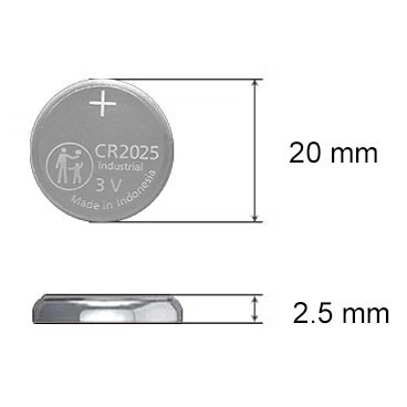
CR2025 Battery: Equivalent, Specifications and Replacements
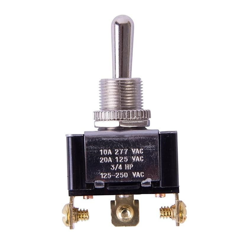
Understanding Toggle Switches: A Comprehensive Guide
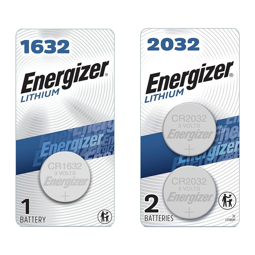
CR1632 vs CR2032: Are CR1632 and CR2032 battery equivalent?

CR1616 Battery Equivalent: Best Replacement Guide


