


- Inicio
- Blogs
- Basic knowledge
- Basic knowledge, functions, parameters, and types of capacitors
Basic knowledge, functions, parameters, and types of capacitors

Capacitors are one of the three major passive components that coexist with resistors and coils. Not only are capacitors used in electrical or electronic circuits, but the circuit would not function properly without them. This is the same for cutting-edge devices such as smartphones and IoT devices, servers and networks, and wireless communication systems. In addition, the performance of capacitors affects the performance of various electronic devices and has become a very important component.
Basic structure of capacitor
Capacitors are components that can store electrical energy and discharge it when necessary. The electric energy (charge) that can be accumulated is small compared to a battery, so when the charge is released (discharge), current can only be supplied for a short time, but charging (accumulation of charge) and discharge can be repeated.
Here is a schematic (model) diagram of a capacitor. A capacitor is constructed by sandwiching an insulator (dielectric) between metal plates (electrodes) in parallel. If a DC voltage is applied between the metal plates (electrodes), charges can be accumulated. This is the electricity storage principle of capacitors. The amount of accumulated charge is called electrostatic capacitance. The electrostatic capacitance C is determined by the dielectric constant ε of the insulator, the surface area S of the electrode, and the thickness d of the insulator.

The role of capacitor
The basic function of a capacitor is to charge and discharge, and the voltage at both ends cannot change suddenly. Its basic properties are to pass AC, block DC, pass high frequency, and block low frequency. According to this property, bypass, decoupling, energy storage and coupling are extended. effect.
1. Bypass and decoupling:
Both bypass and decoupling can be considered as filtering, but the bypass capacitor is generally placed at the input end of the signal to filter out the noise contained in the input signal, while the decoupling capacitor is mainly used at the output end of the signal. Filter out the noise contained in the output signal. Simply put, filtering is to make the AC component (noise) in the DC signal or the high-frequency component in the low-frequency signal flow to the power supply ground through the capacitor.
Decoupling capacitors are usually used at power supply outputs and switching device outputs, and bypass capacitors are usually used at IC power and signal input pins. When laying out, try to keep the filter capacitor (bypass and decoupling) close to the input or output pin of the chip to maximize the purity of the input signal and reduce the interference of noise contained in the output signal to other components.
Theoretically, the larger the capacitance, the lower the impedance, and the higher the frequency of the signal passing through. However, in fact, most capacitors exceeding 1μF are electrolytic capacitors, which contain a high inductance component. As the frequency increases, the impedance will increase. Therefore, we often see a large capacitor and a small capacitor connected in parallel in a circuit. The large capacitor is mainly used to filter out low-frequency noise, while the small capacitor is used to filter out high-frequency noise.

2. Energy storage
Supercapacitors are capacitors specially used to store energy, but general capacitors also have the function of energy storage. For example, bypass capacitors and decoupling capacitors can not only filter out noise in signals, but also have the function of energy storage, just like It is a battery that is constantly being charged and discharged.
3. Coupling
It mainly uses the characteristics of the capacitor to pass AC and block DC, so that the AC signal in the circuit can be transmitted to the next level while blocking the DC signal.

4.Soft start
The characteristic that the voltage at both ends of the capacitor cannot change suddenly is used to prevent excessive voltage or current from damaging the subsequent circuit when the switch is turned on.
In addition to the above functions, the combination of capacitors and resistors can also form integral circuits, differential circuits, timing circuits, bootstrap circuits, etc.
Capacitor voltage and current
Since the capacitor is insulated inside, DC current does not flow. However, as the applied voltage changes, it appears that current flows through the capacitor through charging and discharging. The greater the rate of change of voltage over time, the greater the current flowing through the capacitor, as shown in the following equation.

This section explains the capacitor voltage and current when an uncharged capacitor is charged from a DC power supply through a resistor and then discharged.

On the circuit diagram, if the switch is turned ON on the charging side, the peak current of V0/R1 will flow to the capacitor, and then the current will decrease as the voltage Vc of the capacitor increases. When Vc = V0, charging is completed and the current becomes zero.
Then, if the switch is turned ON on the discharge side, the peak current of V0/R2 will flow to the capacitor, and then the current will decrease as the voltage Vc of the capacitor decreases. When Vc = 0, the discharge is completed and the current becomes zero.

It should be understood that the current Ic of a capacitor depends on the magnitude of the voltage Vc variation of the capacitor.
In addition, when the switch is ON, the current of V0/R will flow, and here, if R=0, theoretically there will be an infinite amount of current flowing through the instantaneous completion of charging and discharging.
However, in reality, due to the influence of the resistance component (ESR) of the capacitor itself or the wiring resistance and reactance components, it will not become infinite. However, the resistance component is much smaller than that of the battery, so it can be said that it is a component that can be charged and discharged instantaneously.
Usage of capacitors
Capacitors have the following characteristics:
① being able to charge and discharge instantaneously;
② DC will not pass, but AC will pass;
③ The higher the frequency, the easier it is for communication to pass through, and methods of using these characteristics are used in the circuit.
1. Discharge circuit
A discharge circuit is a circuit that causes the connected load to act by releasing the accumulated charge in the capacitor. Due to the ability of the discharge circuit to instantly release large currents, it can be used as a flash for cameras or as a backup power source in emergency situations. In the circuit example, if the switch is connected to the power side, the capacitor will be charged; When the charge accumulates to the power supply voltage, charging will stop. If the switch is connected to the load (bulb) side, the capacitor will start discharging and the bulb will light up.

2. Smooth circuit
A smooth circuit is a circuit that smoothes the pulsating current after rectifying AC and converts it into DC. The power circuit is a typical example. By using capacitors, the voltage wave (pulsating, pulsating current) obtained by rectifying the input voltage of AC using a diode bridge (full wave rectification in the circuit example) becomes flat.

3. Decoupling circuit
The decoupling circuit, as its name suggests, is a circuit that utilizes capacitors to separate signal coupling. In this example, as shown in the figure, by adding a capacitor to the signal path containing high-frequency AC components (noise) in the basic DC, only the high-frequency noise components are separated after passing through the capacitor, and then the noise is not transmitted. The purpose of removing switch noise in switching power supplies belongs to this purpose.

4. Coupling circuit
A coupling circuit is a circuit that does not allow direct current components to pass through, but only allows alternating current components to pass through. We hope to use coupling circuits when excluding the influence of DC components (also known as DC truncation, etc.) in the amplification circuit of audio signals.
In addition, there are various usage methods such as resonant circuits, filter circuits, backup circuits, time constant circuits, and power factor improvement.

Characteristics of capacitors
Ideal capacitors only contain electrostatic capacitance components, but actual capacitors contain resistance and inductance components. These parasitic components have a significant impact on the performance of capacitors. The simple equivalent circuit of the capacitor is shown in the figure.
The actual equivalent circuit of a capacitor includes ESR (equivalent series resistance) and ESL (equivalent series inductance). In addition, the electrodes of an ideal capacitor are insulated, but there may actually be several leakage currents.

| Feature project | Describe |
| Electrostatic capacitance © | 1. It is the most basic performance. 2. Several deviations may occur due to manufacturing deviations and other reasons. |
| Equivalent series resistance (ESR) | 1. The value determined by the resistance composition based on the type of medium and the resistance composition of electrodes and terminals. 2. ESR (or tan δ) If it is large, it may cause a malfunction due to the heating caused by the current. 3. In addition, ESR (or tan δ) If it is large, the noise absorption effect will be weakened. |
| Insulation resistance (IR) | 1. The reciprocal of leakage current mainly determined by the type of medium. 2. If the IR is low, the loss caused by leakage current will increase (limited leakage current such as aluminum electrolytic capacitors). |
| Equivalent series inductance (ESL) | 1. Mainly due to the inductance component generated by the structure of the capacitor. 2. If the ESL is large, the inductance component will dominate in the high-frequency region and damage the performance of the capacitor. |
In addition, another important characteristic is the presence of impedance. Simply put, impedance is the ratio of voltage to current in an AC circuit, equivalent to the resistance in a DC circuit. The symbol uses Z, the unit is the same as the resistance, and Ω is used.
The impedance (Z) of a capacitor is represented by equation ①, and the absolute value of impedance can be calculated by equation ②.

According to this equation, the following matters can be understood.
1. In low frequency regions, impedance is almost determined by electrostatic capacitance © It's up to you to decide.
2. At resonance frequency (2 π f L=1/(2 π f C)), impedance is determined by ESR.
3. In high frequency regions, impedance is almost determined by ESL.
If this situation is represented graphically, it is shown in the following figure:

The impedance Z of the capacitor decreases in capacitance before the resonant frequency, while the influence of resonant frequency C and ESL becomes zero, only affected by ESR. After this point, it becomes inductive (ESL) and increases with frequency.
When using capacitors for their main purpose, namely noise absorption (decoupling), the noise absorption effect is determined by impedance, so it is necessary to select components according to the following key points.
4. The frequency of the noise is close to the resonant frequency of the capacitor.
5. Small ESR.
6. When high-frequency noise occurs, the ESL is small.
Parameters of capacitors
Nominal capacity, accuracy, rated voltage, temperature coefficient, equivalent series resistance, equivalent series inductance, leakage current, insulation resistance, loss and frequency characteristics, operating temperature range, service life, etc.
Temperature coefficient: refers to the relative change in capacitance for every 1 ℃ change in temperature within a certain range, which is related to the dielectric material and capacitance structure.
Leakage current: Due to the fact that the capacitive medium is not absolutely non-conductive, the current flowing through the medium at a certain voltage is called leakage current (usually very weak). It is related to environmental temperature, applied voltage, capacitance, manufacturing process, etc.
Insulation resistance: refers to the ratio of capacitor voltage to leakage current. It is related to the dielectric constant, thickness, and area of the medium.
Capacitor loss: The energy consumed by a capacitor due to heating under the action of an electric field, divided into dielectric loss and metal loss, commonly represented by the tangent value of the loss angle.
Equivalent Series Resistance (ESR): In theory, capacitors do not consume energy during the charging and discharging process. However, due to dielectric losses, terminal leads, and other reasons, capacitors consume a portion of energy, which is similar to a resistor and capacitor connected in series. This resistor is called ESR. The presence of ESR can cause a sudden change in the voltage at both ends of the capacitor, reducing its filtering performance. It is one of the very important parameters of capacitance.
Type of capacitor
According to the medium, function, and packaging form, capacitors can be divided into multiple different types. Here, we mainly discuss capacitors of different medium types. There are mainly ceramic capacitors, paper capacitors, mica capacitors, single stone capacitors, thin film capacitors, metallized paper capacitors, oil immersed paper capacitors, aluminum electrolytic capacitors, and tantalum electrolytic capacitors.
Ceramic capacitor: refers to a capacitor with ceramic as the medium, which is rich in raw materials, simple in structure, low in price, and has a wide capacity range (several pF~several hundred μ F) Due to its small size and low loss, it is widely used and can be divided into high-frequency ceramic capacitors and low-frequency ceramic capacitors.

Paper capacitor: Made of very thin special capacitor paper as the medium, aluminum foil or tin foil as the electrode and wound into shape, then connected to the lead wire, and then subjected to diffusion treatment. It is sealed with a shell or epoxy resin. It has a small volume and a large capacity (10pF~tens of) μ F) Wide working range (up to 6.3kV), low cost, but high inherent inductance and dielectric loss, poor stability. Commonly used in low-frequency circuits.

Mica capacitor: An electrode plate is made by spraying a silver layer on a mica sheet. After laminating the electrode plate with the mica medium, it is die-cast in bakelite powder or sealed in epoxy resin. It has the characteristics of low dielectric loss, high insulation resistance, low temperature coefficient, and high accuracy, suitable for high-frequency circuits, but has a large volume and small capacity (0.5~104pF).

Monolithic capacitor: also known as multi-layer ceramic capacitor, abbreviated as MLCC, consists of a multi-layer insulating medium and two conductive metal electrodes. According to the standards of the American Electrotechnical Association (EIA), MLCC of different dielectric materials can be classified into three categories based on temperature stability: ultra stable level (Class I), such as COG or NPO; Stable level (Class II), such as X7R; Capable of using Class III, such as Y5V. Among them, NPO has the best stability and hardly changes with temperature, time, and voltage, but its maximum capacity is only 100 nF, suitable for high-frequency and ultra-high frequency circuits that require high stability and reliability. X7R, also known as temperature stable ceramic capacitors, has a capacity change of ± 15% when the temperature is between -55 ℃~+125 ℃, but the capacity does not change linearly, with a capacity range of 300pF~3.3 μ F. The stability of Y5V is worse than that of X7R, with a capacity change of -82% to+22% within the range of -30 ℃ to+85 ℃.

Thin film capacitor: Using metal foil as electrode and electronic grade plastic film as medium. According to the different dielectric materials, it can be divided into polyethylene capacitors, polypropylene capacitors, polystyrene capacitors, polycarbonate capacitors, and polyester capacitors. Among them, the insulation resistance of polystyrene capacitors is as high as 100G Ω, with extremely low leakage current, low dielectric loss, and high accuracy. They can replace mica capacitors in some high-frequency circuits, but their volume is large and their operating temperature is high.

Polypropylene capacitors (CBB capacitors) have similar performance to polystyrene capacitors, but they are small in size, low in price, and have a slightly higher temperature coefficient than polystyrene.

Aluminum electrolytic capacitor: One of the most common capacitors, made by using an aluminum cylinder as the negative electrode, containing a liquid electrolyte, and inserting a curved aluminum strip as the positive electrode. Large capacity (capable of achieving Class F), extremely low cost, but with high leakage current and poor stability, positive and negative electrodes are widely used in power filtering and low-frequency circuits.

Tantalum capacitor: It is a product with a small volume and can reach a larger capacity among all capacitors, but due to the scarcity of tantalum raw materials, the price is relatively expensive. Tantalum capacitors have high insulation resistance, low leakage current, good temperature characteristics, positive and negative electrodes, and are often used in high demand situations.

Safety capacitor: refers to a capacitor that, after failure, will not cause electric shock and does not endanger personal safety. It is mainly used in switching power supplies and is divided into X capacitors and Y capacitors. X capacitance refers to the capacitance that spans between the zero line and the live line, mainly used for differential mode filtering. Y capacitance refers to the capacitance between the zero line and ground, and between the live line and ground, mainly used for common mode filtering.

Articles you may also like
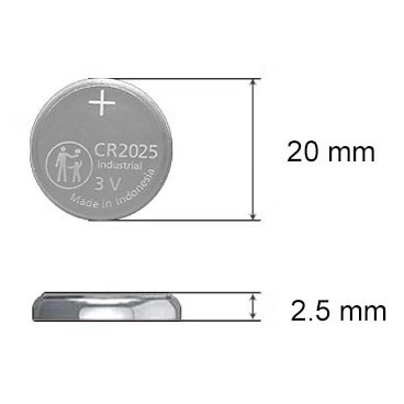
CR2025 Battery: Equivalent, Specifications and Replacements
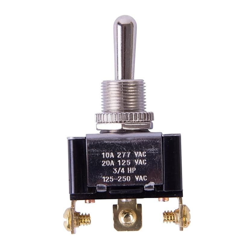
Understanding Toggle Switches: A Comprehensive Guide
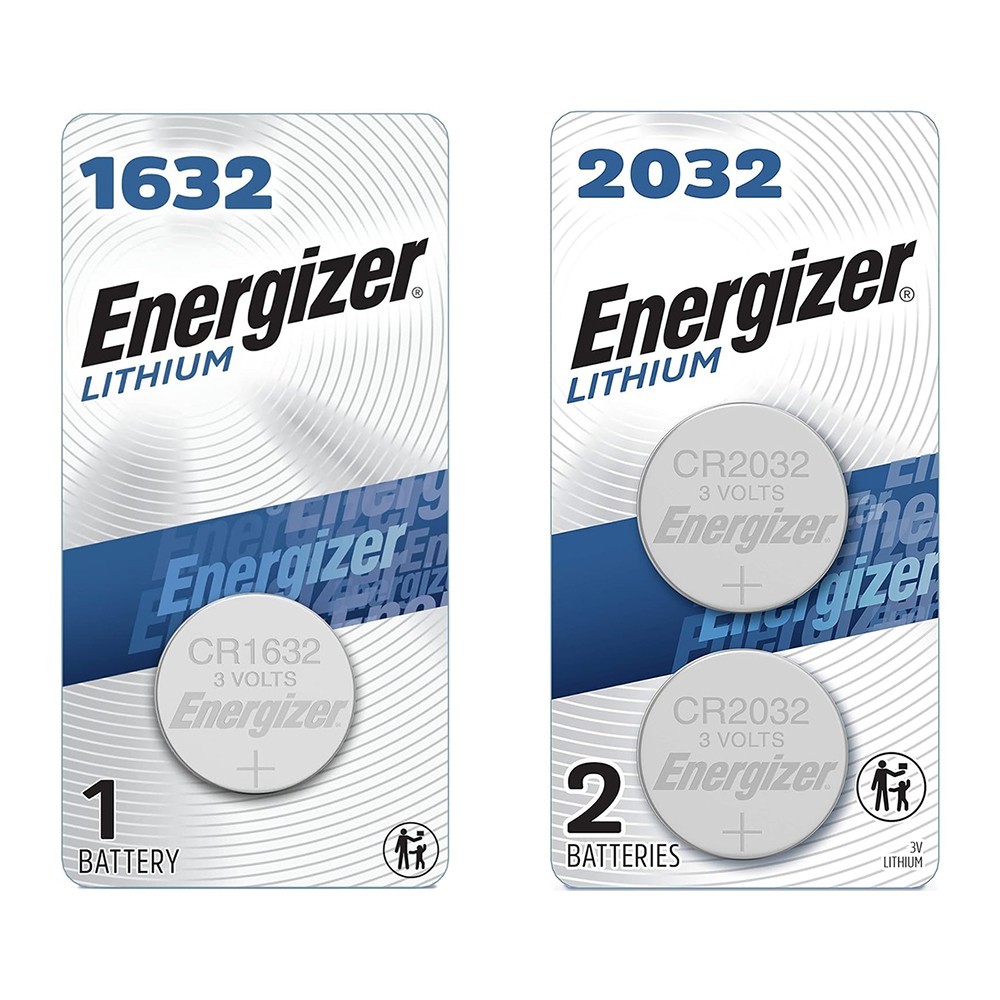
CR1632 vs CR2032: Are CR1632 and CR2032 battery equivalent?

CR1616 Battery Equivalent: Best Replacement Guide


