


- Home
- Blogs
- Basic knowledge
- The principle, symbol and error of resistance
The principle, symbol and error of resistance
Initial resistance
1. Basic principles
The resistor is composed of three parts: the resistor body, the frame and the terminal (the resistor body and the frame of the solid resistor are combined into one), and it is only the resistor body that determines the resistance value. For a resistor body with uniform cross-section, the resistance value is

In the above figure, ρ is the resistivity of the resistive material (ohm·cm); L is the length of the resistor body (cm); A is the cross-sectional area of the resistor body (square centimeters).
The thickness d of the thin film resistor is very small and difficult to measure accurately, and ρ changes with the thickness, so it is regarded as a constant related to the thin film material and is called film resistance. In fact, it is the resistance value of the square film, so it is also called square resistance (ohm/square). For uniform films

In the above figure, W is the width of the film (cm). Usually Rs should be within a limited range. If Rs is too large, it will affect the stability of the resistor performance. Therefore, grooves are used for cylindrical resistors, and circuitous patterns are etched for planar resistors to expand their resistance range and fine-tune the resistance.
The volt-ampere characteristic uses a graphic curve to represent the relationship between the voltage and current at the end of the resistor. When the voltage and current are proportional (the characteristic is a straight line), it is called a linear resistance, otherwise it is called a nonlinear resistance.
Parameters and characteristics: The main parameters that characterize resistance characteristics include nominal resistance value and its allowable deviation, rated power, load characteristics, resistance temperature coefficient, etc.
2. The symbol of resistance
The circuit symbol of the resistor is R, and the potentiometer is "RP", that is, adding a character "P" after R to indicate that it has an adjustment function. The basic unit of resistance is ohm, represented by the Greek letter "Ω". Commonly used units include kiloohm (kΩ), megaohm (MΩ), and milliohm (mΩ).

Common electrical symbols for resistors
Classification and characteristics
1. Classification according to volt-ampere characteristics
For most conductors, at a certain temperature, their resistance remains almost constant at a certain value. This type of resistance is called linear resistance. The resistance of some materials changes significantly with current (or voltage), and its volt-ampere characteristic is a curve. This type of resistance is called a nonlinear resistor. Under the action of a given voltage (or current) of a nonlinear resistor, the ratio of voltage to current is the static resistance at that operating point, and the slope on the volt-ampere characteristic curve is the dynamic resistance. The way to express the characteristics of nonlinear resistors is complicated, but these nonlinear relationships are widely used in electronic circuits.
2. Classification by material
There are many types of resistors, with large differences in appearance, price, and performance, and they are suitable for different circuit situations. Types commonly used in analog and digital circuit systems include carbon film resistors, metal film resistors, wirewound resistors, chip resistors, etc.
2.1. Carbon film resistor
Carbon Film Resistor uses high-temperature vacuum coating technology to deposit carbon on the surface of a white fine ceramic rod to form a conductive film. The conductive film is then spirally turned to form a spiral groove, and finally the surface is painted with grass green or earthy yellow. Epoxy resin insulating coating of equal colors, the internal structure of the carbon film resistor is as shown in the figure below

Internal structure of carbon film resistor
Carbon film resistors generally use 4 color rings for parameter marking; the error rings are mostly gold (±5%), silver (±10%) and natural color (±20%). The resistance value of commonly used carbon film resistors is in the range of 0.1Ω to 10MΩ.
Carbon film resistors are cheap and have good long-term working stability. They are the first choice for consumer electronics products (such as low-power switching power supplies and toys) that give priority to cost factors, low index requirements, and large production quantities. Its characteristics of large unit volume, high noise, high temperature coefficient and low precision determine that it is not suitable for low-frequency analog circuits and low-noise circuits.

carbon film resistor
2.2. Metal film resistor
Metal film resistors (Mctal Film Rocicton) are made by depositing an alloy film on the surface of a hollow ceramic tube and then processing the alloy film into grooves. The denser the grooves processed into the metal film, the greater the equivalent length L of the resistance and the smaller the cross-sectional area S. According to the calculation formula of resistance value R=p·l/S, it can be seen that the resistance value will be greater.
The unit price of metal film resistors is slightly higher than that of carbon film resistors, but they have low temperature coefficient, high precision, small size, and the bulk purchase price is less than 0.01 yuan/piece, so they are widely used. The outer skin of metal film resistors is mainly blue or blue-green, and the parameters are mostly marked with a 5-color ring.

Metal Film Resistors
The shapes of carbon film resistors and metal film resistors are similar and are easily confused. They can be distinguished by the background color of the resistor body, the color of the error ring, and the film color: when the primer on the resistor surface is scraped off with a blade to observe, the film of the carbon film resistor is black. The film of a metal film resistor is white.
2.3. Wirewound resistor
Wire Wound Resistor is made of nickel-chromium alloy wire, constantan wire, manganese copper wire and other resistance wires wound on the surface of a porcelain tube. According to the resistance value calculation formula R=p·l/S, it can be seen that the more turns the resistance wire is wound, the greater the equivalent length l of the resistor body, and the greater the resistance value. In order to obtain a wirewound resistor with a large resistance value, a resistance wire material with a large resistivity can be used for winding.
The production processes of wirewound resistors and inductors are relatively close, so there are obvious parasitic inductances (the more turns, the greater the parasitic inductance) and distribution parameters, which are not suitable for high-frequency circuits. Wirewound resistors can be used in two different working situations: high power and high precision.
1), power type wirewound resistor
The alloy wire used to wind power type wirewound resistors is relatively thick, and the load rating they can withstand is generally above 1W. The resistance value range of power wirewound resistors is 0.1Ω~100Ω, and the common accuracies include ±5%, ±2%, and ±1%.
The shells of power wirewound resistors are mostly made of white ceramic or cement materials. Due to the high heat generation, it is not recommended to install them close to the surface of the circuit PCB. To increase the heat dissipation area.
Tip: Wirewound resistors with excessive power must be forced to actively dissipate heat using air cooling or oil cooling to avoid overheating and damage to the resistor.
2), Precision wirewound resistor
The accuracy of precision wirewound resistors can reach ±0.01%, and the temperature coefficient is less than 10-6ppm/℃. Due to the small power it can withstand, precision wirewound resistors are often made of thin resistance wires, and the upper limit of their resistance values can reach the order of MΩ .

Precision wirewound resistor
2.4. Chip resistor
SMD Chip Resistor is made by uniformly mixing metal powder and glass glaze powder, using a binder to form a paste, printing a resistive film on the surface of the ceramic substrate and sintering it at high temperature. It is moisture-proof, high-temperature resistant and has a small temperature coefficient. , low production cost and other advantages.
The chip resistor adopts a leadless package. The shape of the chip resistor is as shown in the figure. It is very small. Electronic products generally pursue "small, thin and light". Under the conditions of extremely high requirements on PCB size and system volume, Chip resistors have begun to completely replace low-power plug-in resistors.
There are many types of chip resistors, and the common models are 0805 (outline size: 0.08in×0.05in, lin=2.54cm) and 0603. In addition, there are other models such as 2510, 2225, 1812, 1210, 1206, 0402, 0201, 01005, etc. The smaller the value, the smaller the PCB surface area it occupies, and the more difficult it is to perform soldering and desoldering operations.
In the chip resistor shown in the figure, "R047" means the resistance value is 0.047Q=47mΩ, "1502" means the resistance value is 150×102=15kΩ, and "103" means the resistance value is 10×103=10kΩ.

Chip resistors with the same resistance
2.5. Special resistors
2.5.1. Fuse resistor
Fuse resistor: Also called fuse resistor, it plays the dual role of resistor and fuse under normal circumstances. When a circuit fails and its power exceeds the rated power, it will melt like a fuse and disconnect the connected circuit. Fuse resistors generally have small resistance values (0.33Ω~10KΩ) and low power. Commonly used models of fuse resistors include: RF10 type, RF111-5 fuse resistor symbol type, RRD0910 type, RRD0911 type, etc.

Fuse
Inside the fuse (also called a fuse), a fuse made of low-melting point alloys such as lead, antimony, and tin is a special resistor. When the operating current is not large, a fuse with very low internal resistance has minimal impact on the circuit; when the current increases abnormally and exceeds the rated current, the instantaneous heat Q=I2Rt generated by the fuse is large enough to cause it to fuse itself and immediately cut off the power supply. circuit and implement protection. The fuse is encapsulated in a glass or ceramic tube shell, which not only prevents the fuse from splashing around or pulling out arcs when it blows, but also facilitates quick replacement when damaged. Common fuse shapes and electrical symbols are shown in the figure. The diameter of the fuse is mainly divided into two specifications: 5×20mm and 6×30mm. The latter has a larger fusing current, generally above 5A. In order to facilitate replacement, the fuse is rarely soldered directly into the PCB.

Electrical symbol for fuse
1) Parameters of fuse
The parameters of the fuse are printed on the surface of the metal shell at both ends of the glass tube, including rated current, rated voltage, fusing speed, etc.
Rated current: The rated current is the most critical parameter of the fuse. It is the effective value of the current that causes the fuse to fuse. It mainly includes 30mA, 50mA, 63mA, 8OmA, 100mA, 200mA, 250mA, 500mA and 1A, 1.5A, 2A, 2.5A. , 3A, 4A, 5A, 6A, 7A, 8A, 10A, 12A and other specifications.
Rated voltage: In low-power applications, the rated voltage of the fuse when working is generally 250V.
Fusing speed: Fusing speed is divided into fast (F), extra fast (FF), extra slow (TT), slow (T) and other types.
The parameter information of the commonly used fuse in CRT color TV power supply is "T3.15AL250V", which means that the rated voltage of the fuse is 250V, the rated current is 3.15A, and it is a slow blow type. L means that the fuse of the fuse has low voltage breaking capability. . The slow-blow fuse can effectively eliminate the short-duration peak current exceeding 3.15A at the start of the power supply to prevent the fuse from being accidentally blown.
2), the working circuit of the fuse
The connection method of the fuse in the circuit is very simple. It can be directly connected in series to the circuit branch that needs overcurrent protection.
The figure shows the working circuit of the fuse indicating fault status.
VD1 is a common cathode dual-color LED with three pins: red anode, green anode, and common cathode. Resistor R is the current limiting resistor of VD1 to avoid damage to the LED due to excessive current. The red anode of the LED is connected to the power input terminal Vin, and the green anode is connected to the power output terminal Vout. The fuse F is connected across Vin and Vout. When the power supply current is normal, F1 is turned on, both red and green LED groups light up normally, and the mixed indication status is brown. When an overcurrent fault occurs in the power supply, F1 fuses, the green LED goes out, and the entire VD1 displays red light, reminding the staff to check the circuit fault and replace the fuse.

Fuse operating circuit for fault status indication
2.5.2. Sensitive resistor
Sensitive resistor: refers to its resistance value that is sensitive to certain physical quantities (such as temperature, humidity, light, voltage, mechanical force, gas concentration, etc.). When these physical quantities change, the resistance value of the sensitive resistor will change accordingly. Changes occur when physical quantities change, showing different resistance values. According to sensitivity to different physical quantities, sensitive resistors can be divided into heat-sensitive, moisture-sensitive, light-sensitive, pressure-sensitive, force-sensitive, magnet-sensitive and gas-sensitive types of sensitive resistors. The materials used in sensitive resistors are almost all semiconductor materials, and these resistors are also called semiconductor resistors.
1), thermistor
There is a close relationship between the resistance value of a resistor and temperature. The temperature coefficient αγ=(R2-R1)/(R1·(t2-t1)) is commonly used to measure the temperature stability of a resistor. In the formula, the unit of αγ is ℃-1; R1 and R2 are the actual resistance values measured when the resistor is at temperatures t1 and t2 respectively, and the unit is Ω. All resistive materials have a temperature coefficient. The cold state resistance of incandescent bulbs is much smaller than the calculated rated resistance value of the bulb, and phenomena such as low-temperature superconductivity (the resistance value disappears when the temperature drops to a certain level) are all typical cases of temperature coefficient.
Tip: The smaller the temperature coefficient of the resistor, the better its temperature stability. In circuit design, priority should be given to selecting a resistor with a small temperature coefficient. Taking advantage of the large temperature coefficient of some materials, a temperature-sensitive thermistor can be made ( Thermal Resistor). The resistance value of the thermistor changes regularly with changes in ambient temperature, and is often used to measure temperature or perform temperature control.
Thermistors can be divided into two types: positive temperature coefficient thermistors and negative temperature coefficient thermistors.
Positive temperature coefficient (PTC) thermistor: When the ambient temperature rises, the resistance value of PTC thermistor increases rapidly. In addition to its temperature measurement function, PTC thermistors are often used in circuit units such as delayed start, constant temperature heating, and overcurrent protection.

PTC thermistor
Negative temperature coefficient (NTC) thermistor: The shell of NTC thermistor is generally black. When the ambient temperature increases, the resistance value of NTC thermistor decreases rapidly, and it is mostly used in high-precision temperature detection processes, such as overheat protection digital thermometers for rechargeable batteries and power transistors. Power NTC thermistors are often used in switching power supplies and motor starting control circuits for surge suppression.

NTC thermistor and electrical symbols
Tip: Metal film resistors have a small positive temperature coefficient, and carbon film resistors have a large negative temperature coefficient.
2), Photoresistor
Photo resistor (Photo Resistor) uses the photoelectric effect of semiconductor materials to work. The appearance and internal structure are shown in the figure, and the electrical symbols are shown in the figure. Under shading conditions, the resistance value of the photoresistor is very high; when illuminated by light of a specific wavelength, the resistance value of the photoresistor decreases and the conductivity increases.
The electrode materials of photoresistor include cadmium sulfide, cadmium selenide, cadmium sulfide, arsenide, zinc sulfide, etc. The sensitive wavelengths of different materials are different. The photosensitive surface diameter of the photoresistor is available in various specifications such as 3mm, 4mm, 5mm, 7mm, 10mm, 12mm, and 20mm. In order to obtain the largest possible photosensitive area and improve light sensitivity, an "S"-shaped comb-shaped meshing line as shown in the figure is used between the two electrode surfaces.

Photoresistor and electrical symbols
2.5.3. Potentiometer
A potentiometer is a special resistor that can adjust the resistance value by changing the position of the sliding contact.
Depending on the rotation angle of the shaft, potentiometers can be divided into two categories: single-turn potentiometers (the knob adjustment angle is less than 360°) and multi-turn potentiometers (the knob adjustment angle is greater than 360°). The latter has a higher resolution.
The arc-shaped resistor inside the potentiometer leads to two pins, and the contact brush is connected to the middle tap pin. The resistance value of the resistor is the nominal value of the potentiometer. When the contact brush rotates around the potentiometer's axis on the surface of the resistor, the resistance value between any resistor pin and the middle tap pin will change. The resistance value of the resistor body always remains the nominal value of the potentiometer.

Potentiometers and electrical symbols
2.5.4, exclusion
If a circuit needs to use resistors with the same resistance value (or a certain resistance value pattern), consistent performance, the same temperature coefficient, and high stability, multiple resistors are often integrated into a chip-like packaging structure. The resistor exclusion occupies a small PCB space and has a low unit cost, which can greatly improve the system integration and production and assembly efficiency of electronic products.
The resistance value of the resistor is generally marked with a 3-digit value: the 1st and 2nd digits are significant figures, and the 3rd digit is the magnification.
Among the parameters marked on the single-in-line type resistor shown in the figure, "103" means that the resistance value of each resistor inside the resistor is 10×103=10kΩ, "A" represents the resistor type, and "G" represents the internal resistance of the resistor. The error range is ±2%.
The table below shows the single in-line resistor, error code and corresponding error range.

Direct insertion exclusion error code
Parameters and selection
The main parameters of a resistor include nominal value, error range (accuracy), rated power, package shape, etc. When designers choose appropriate resistor parameters and specifications for a circuit, there is no unified reference standard to follow, and a certain amount of experience is often required. accumulation. Obviously, being fully familiar with the relevant parameters of resistors will help designers make relatively good resistor selection plans.
1. Nominal value
The nominal value is the key parameter of the resistor. The nominal value of the resistor needs to have the 2-digit value of the E24 series shown in the table or the 3-digit value of the E192 series shown in the table. For digital circuits, you can choose either E24 series metal film resistors or E12 series carbon film resistors; in analog circuits, if the theoretical calculation results deviate greatly from the E24 series resistance values, you can choose the nominal values of the E48, E96, and E192 series. To reduce the impact of parameter errors on circuit performance.
The selection of the nominal value of the resistor is based on the principle of being close to the theoretical calculation results. It is not advisable to pursue high-precision, non-standard resistor products one-sidedly.
The following techniques can be used instead:
By connecting several resistors in parallel or in series, certain special resistance values can be obtained; by adjusting the potentiometer (variable resistor), the resistance value reaches the theoretical calculation result.
Tip: For special resistor nominal values such as the multimeter's internal voltage divider resistor, non-standard resistors can be customized from the manufacturer, but they are expensive.
1.1. Direct marking method
1). Print the resistance value and error directly on the resistor with numbers and letters (no error is marked as an allowable error of ±20%). There are also manufacturers that use customary notation, such as:
3Ω3 I means the resistance value is 3.3Ω and the allowable error is ±5%
1K8 means the resistance value is 1.8KΩ and the allowable error is ±20%
5M1 Ⅱ means the resistance value is 5.1MΩ and the allowable error is ±10%
2). Conventional 3-digit notation method: XXY
XXY=XX*10Y The first two digits of XX represent 2 significant digits, and the last digit of Y represents the power of 10. Mostly used in E-24 series. The accuracy is ±5% (J), ±2% (G), and some manufacturers also use ±1% (F). Examples are as follows:

Example of 3-digit notation method
3). Conventional 4-digit notation method: XXXY
XXXY=XXX*10YThe first three digits of XXX represent 3 significant digits, and the last digit of Y represents the power of 10. Mostly used in E-24, E-96 series, the accuracy is ±1% (F), ±0.5% (D). Examples are as follows:

Example of 4-digit notation method
4), 3-digit multiplier code (Multiplier Code) notation method: XXY
xxxy=xxx*10y The first two digits of XX refer to the code of the valid number. The specific value is found from the E-96 multiplier code table and converted to xxx; the last digit of Y refers to the code of several powers of 10, specifically the code from E-96 Look up the resistance code table and convert it to y. For use in E-96 series. The accuracy is ±1% (F), ±0.5% (D). Examples are as follows:

Example of 3-digit multiplier code notation
E-96 multiplier code table E-96 resistance code table 4R indicates the decimal point position. When the unit is Ω, R indicates the decimal point position. Examples are as follows:

E-96 Multiplier Code Table Example

E-96 multiplier code table

E-96 resistance code table
5), m represents the decimal point position
When the unit is mΩ, m represents the decimal point position. Examples are as follows:

1.2. Color marking method
Paint the color rings of different colors on the resistor (or capacitor) to indicate the nominal value and allowable error of the resistor (capacitor). The values corresponding to each color are shown in the table.
How to identify four-ring resistors

Identification of five-ring resistor

How to use the above table: Four-ring resistor: One-ring number (tens digit) "Red" Second-ring number (one's digit) "Orange" * multiplier "Black" error "Gold"
For example; red, orange, black and gold=23*10^0=23Ω(±5%)
Five-ring resistor: One ring number (hundreds digit) "Red" Two ring number (tens place) "Blue" Three ring number (ones digit) "Green" * multiplier "Black" error
Example: red, blue, green, black and brown=265*10^0=265Ω(±1%)
Allowable deviation: The maximum allowable deviation between the actual resistance value and the nominal resistance value, expressed in percentage. Commonly used ones are ±5%, ±10%, and ±20%. The precision ones are less than ±1%, and the high-precision ones can reach 0.001%. Accuracy is determined by both allowable deviation and irreversible resistance changes.
Rated power: The maximum power allowed to be dissipated by the resistor in continuous operation at the rated temperature (maximum ambient temperature) tR. The maximum working voltage is also specified for each resistor. That is, when the resistance value is high, even if the rated power is not reached, the maximum working voltage cannot be exceeded.
2. Error range
There will be more or less error between the actual value of the resistor and the nominal value. The allowable error range of ordinary resistors includes three categories: +20%, ±10%, and ±5%, while the allowable error range of precision resistors can reach A0.01%. The smaller the error range of the resistor, the higher the price. Therefore, the designer should comprehensively consider the application background of the hardware circuit (testing/mass production), indicator accuracy, product use and price, maintenance and replacement, and other factors to choose the optimal one. resistance accuracy, do not blindly pursue high accuracy.
1) In digital circuits and microcontroller interface circuits, selecting resistors with an error range of ±20% or ±10% can already meet the requirements.
2) In analog circuits that need to ensure measurement accuracy, resistors with an error range of ±0.01% to ±1% can be selected according to the product grade.
3) In the switching power supply and control device circuits, resistors with an error range of ±0.5%~±5% can be selected.
4) In cost-sensitive circuits such as toy circuits, resistors with an error range of ±20% are preferred.
3. Rated power
Within the rated temperature conditions and temperature rise range, the maximum power that the resistor is allowed to consume when it operates continuously in the circuit for a long time without damage is the rated power of the resistor. For resistors of the same material, the greater the rated power, the greater the volume and mass, and the greater the heat generation.
The rated power of resistors in electronic circuits mainly includes 1/16W, 1/8W, 1/4W, 1/2W, 1W, 2W and other types. The rated power of the resistor should exceed 150%~200% of the dissipated power (P=IR) obtained through theoretical calculation. Since the power of the resistor is highly related to the volume and price, do not choose a resistor with an excessively large rated power. On the one hand, the cost will be significantly increased, and on the other hand, it will occupy too much PCB area.
Tip: The power of the resistor inserted in the circuit PCB needs to be controlled within 5W, and should be kept at a certain distance from the PCB surface to leave an airflow channel. Otherwise, the resistor that generates serious heat will cause the PCB copper foil, pads, and surrounding components to burn. , breakage and other damage.
Tips: Resistors with better heat dissipation conditions (with heat sinks, forced air cooling or water cooling) can withstand actual power slightly higher than the rated power.
4. Package appearance
In-line resistors have two packaging structures: axial (AXIAL) and radial (RADIAL), as shown in Figure 2-2-07.
The axially packaged resistors mainly use the color marking method for parameter marking, while the radially packaged resistors use the direct marking method or the digital method for parameter marking.
(a) Axial package resistor
(b) Radial package resistor
Related articles
Articles you may also like
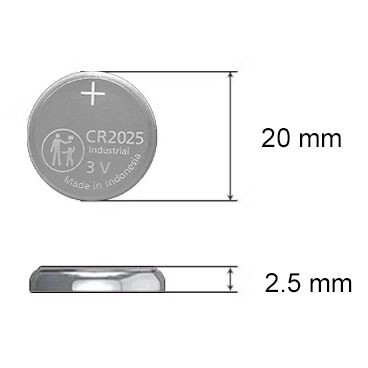
CR2025 Battery: Equivalent, Specifications and Replacements
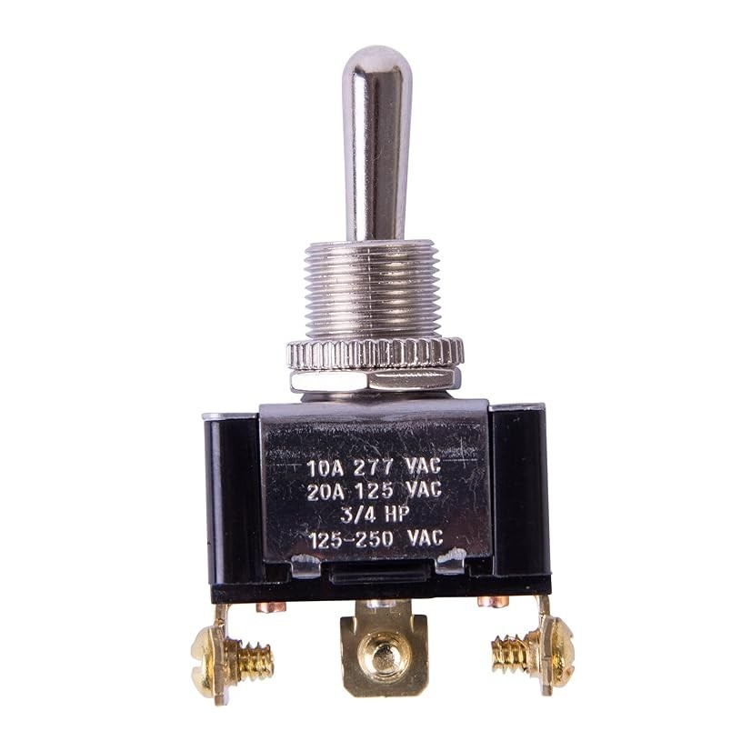
Understanding Toggle Switches: A Comprehensive Guide
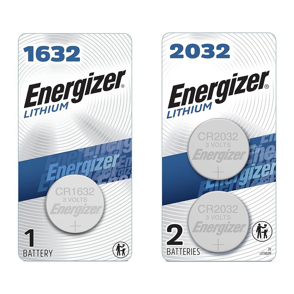
CR1632 vs CR2032: Are CR1632 and CR2032 battery equivalent?

CR1616 Battery Equivalent: Best Replacement Guide

-

-

-

-

-

panasonic-electric-works
General Purpose Relays DPST-NO/NC (1 Form A, 1 Form B) 5 A 5VDC
-

-

-

-
